So at this point I basically started over, having learned from my mistakes. I had finished assembly a complete finger as a prototype and felt confident I could machine all the rest of the parts. over the course of the next several months I did just that, refining my ‘MillDroid’ CNC software and building new tools along the way. Here are some of the highlights along the journey….
Without the ability to weld aluminum, sometimes I wasted a lot of metal. The carpals and metacarpals of the hand would have probably been more efficient to machine from separate pieces, but I pushed everything through as a single pice of metal whenever possible for strength and ease of assembly later.
Pieces such as this, while difficult to machine, were much stronger that if they have been separate pieces held together with a screw. Plus, being true to the original arm prop, if I didn’t see a screw holding it, that meant I tried my best to machine it as the original was, no matter how difficult.
I did do a very small amount of aluminum soldering. I was never happy about the strength of these joints, but again, wanted to stay true to the original.
The ‘palm plate’ or metacarpal plate served as the base of the hand like a wrist.
This plate was to have a very ‘organic’ shape with all curves. I probably could have written some CNC code for arcs, but being able to cut complex curves began to interest me and I was immediately sidetracked by the concept.
I detoured from the project for a few weeks to design and write some custom software that would allow me to draw bezier curves and output them directly to my MillDroid CNC application. This gave me yet another custom piece of software that I could enhance over the years whenever I felt the need. Of course, I could only blame myself if I found any bugs, but I can live with that. The curve editing application I wrote became almost a full fledges CAD/CAM app over time and I named it Pathfinder. You can find details on it on this blog under the Software/Pathfinder section.
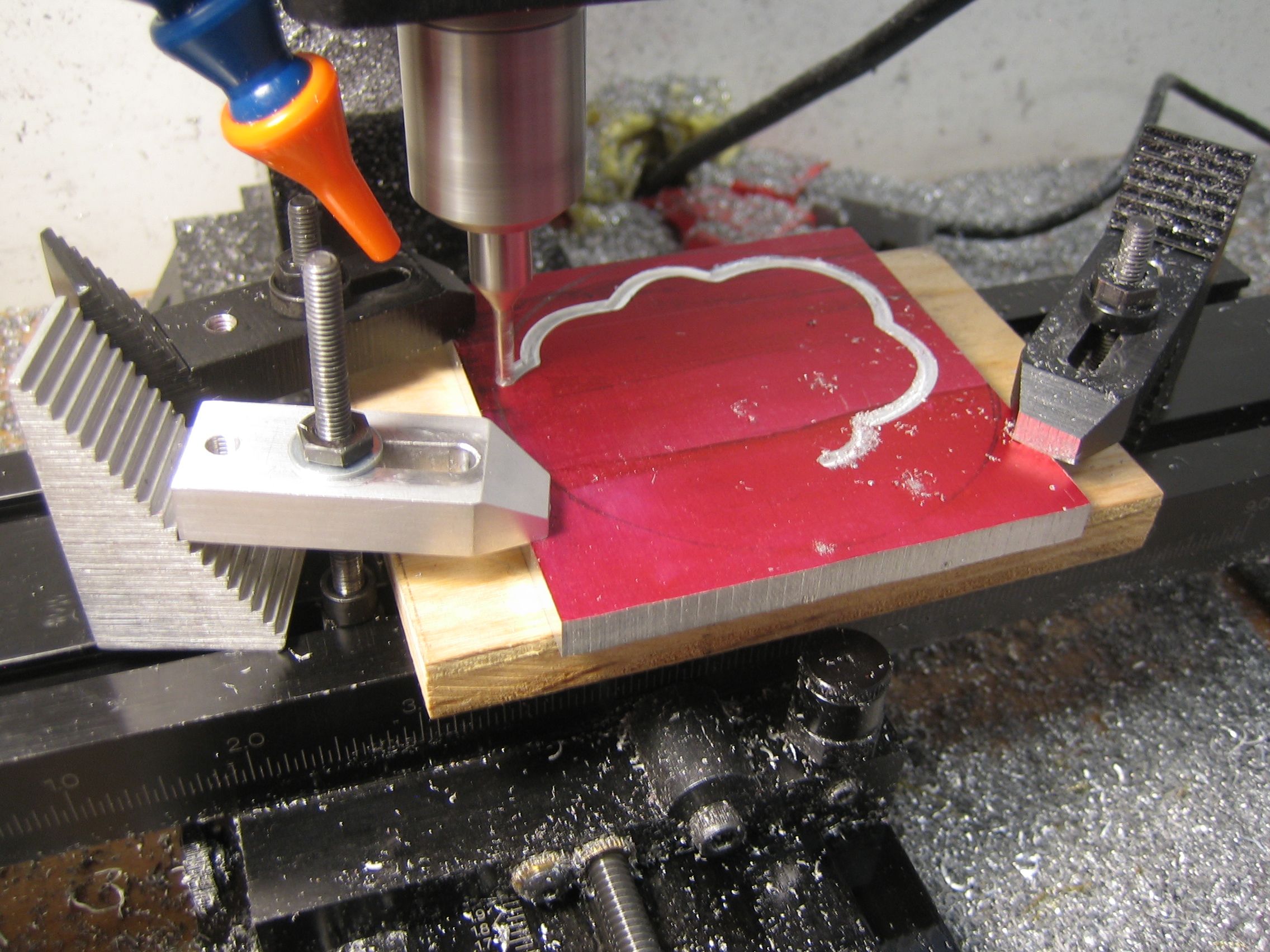
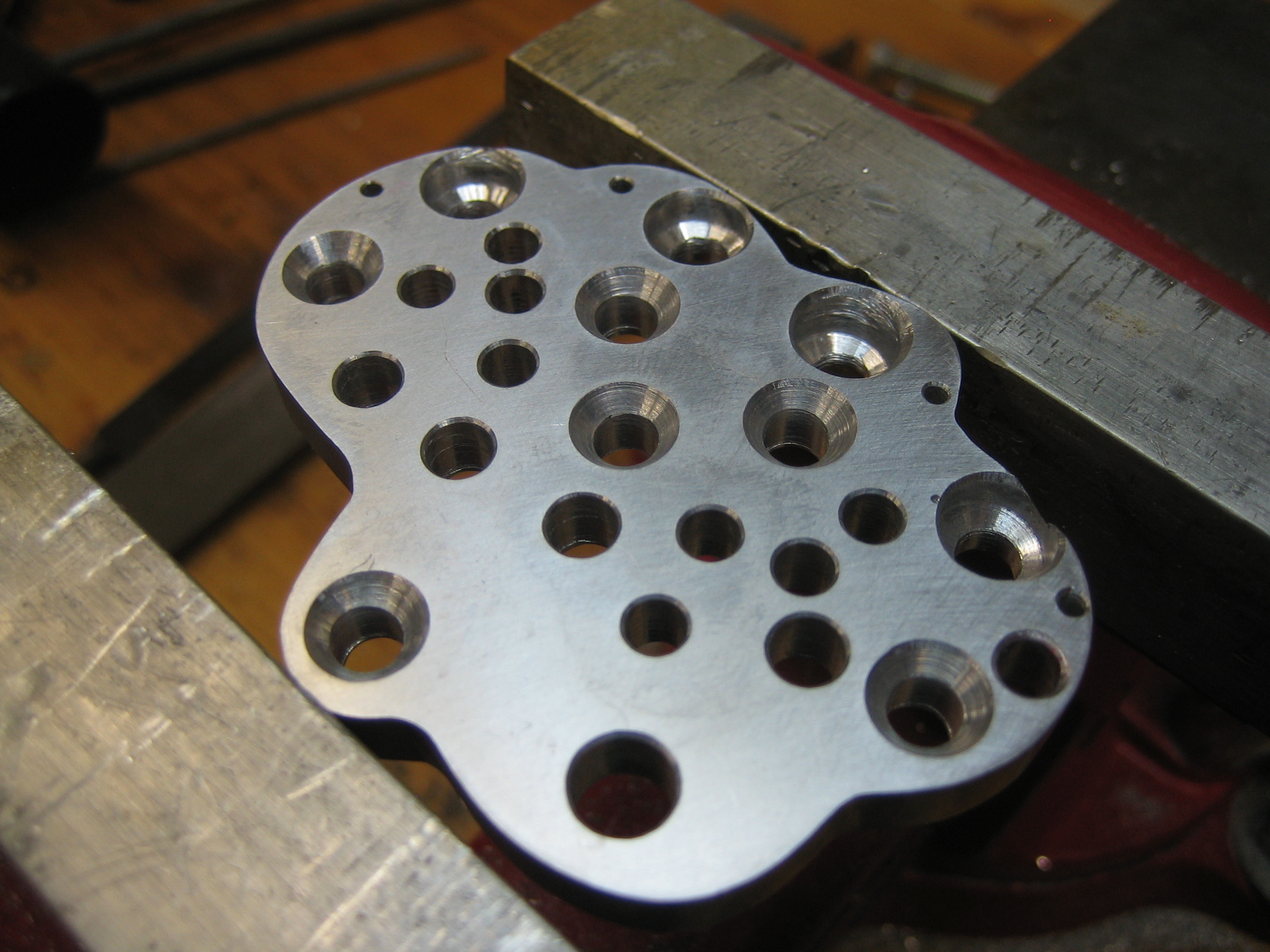
A few dozen precise holes for all the metacarpals, cables and pulleys and we’re good to go!
As I made more pieces, a nightly ritual became filling my compound tumbler with media and lubricant, letting it run overnight, then a day or so later refining the tumbler media to finer and finer compounds to soften and polish the pieces. Tumbing metal is as much a science as an art, and a few times my tumbler ‘shook itself to pieces’ overnight, surprising me in the morning with a pile of media and timber parts on the floor of my shop. It’ a very time consuming operation (and messy) but interesting to try to master. Unfortunately I didn’t take many pictures during the tumbling process.
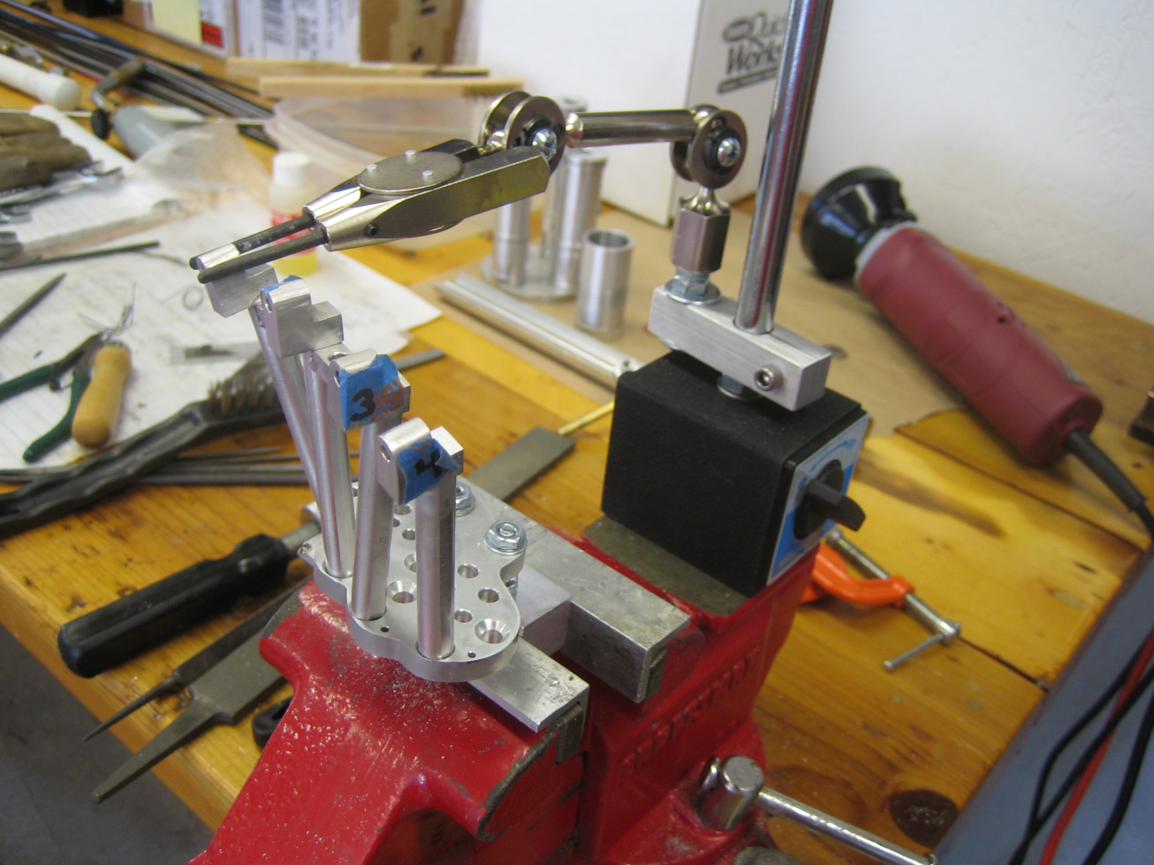
I set up a few jigs for holding pieces during ‘aluminum welding’ (closer to silver soldering, actually) to maintain the critical angles for pieces.
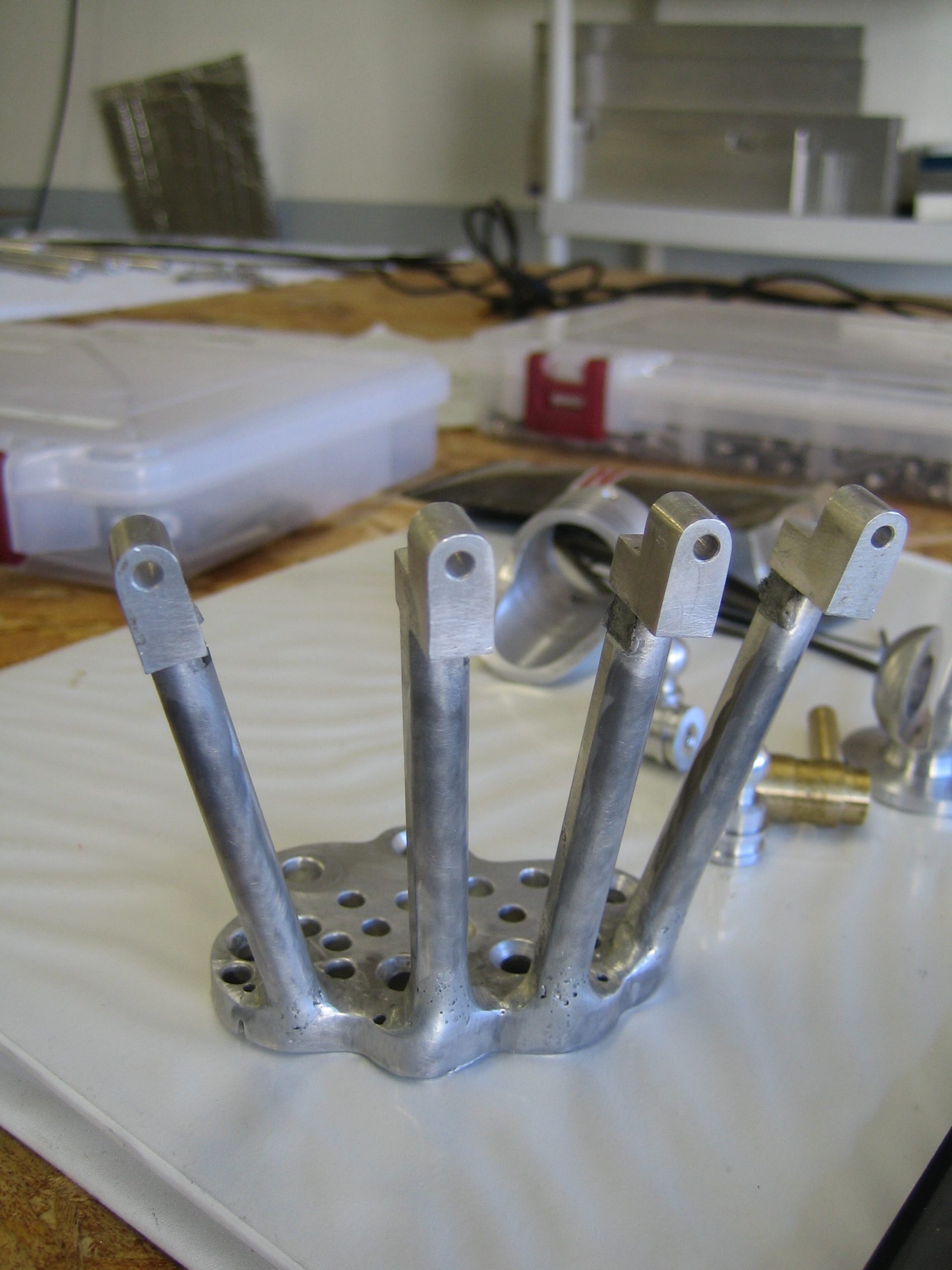
A LOT of work went into getting the ‘aluminum welding’ correct, maintaining the shape of the molten metal and keeping the shape proper. I was very pleased it worked out, because going into this part of the process I was very nervous about keeping everything accurate.
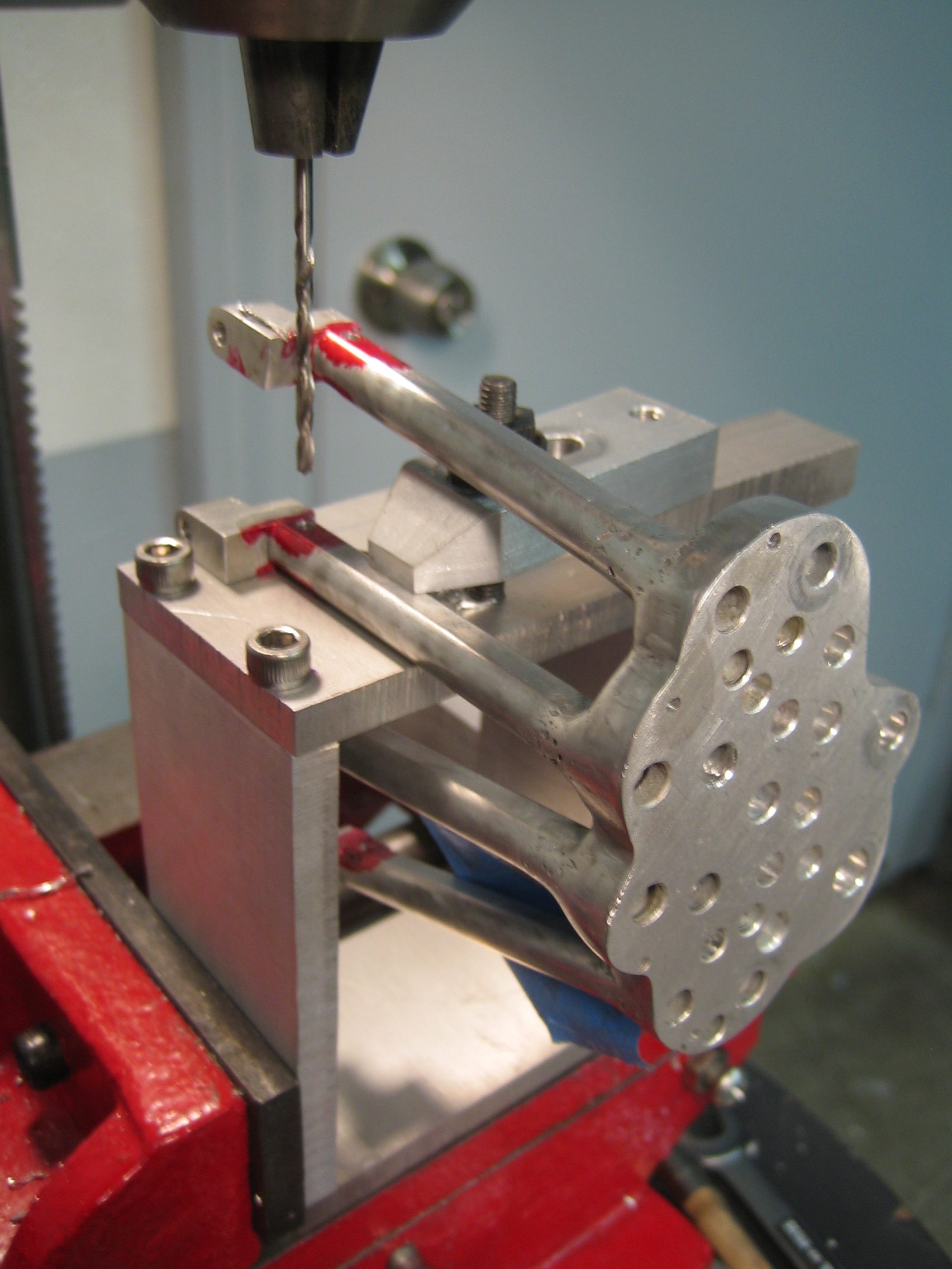
I would sometimes get hung up on ‘order of operations’, that is, should I drill certain holes first, risking them being off, or wait until something was in place. This was one of those times. I couldn’t drill the cabling holes until the pieces were in place in case the move a bit, so that meant doing all the drilling while working around all the already mounted metacarpals. It became quite the jigsaw puzzle of operations but always stayed interesting.
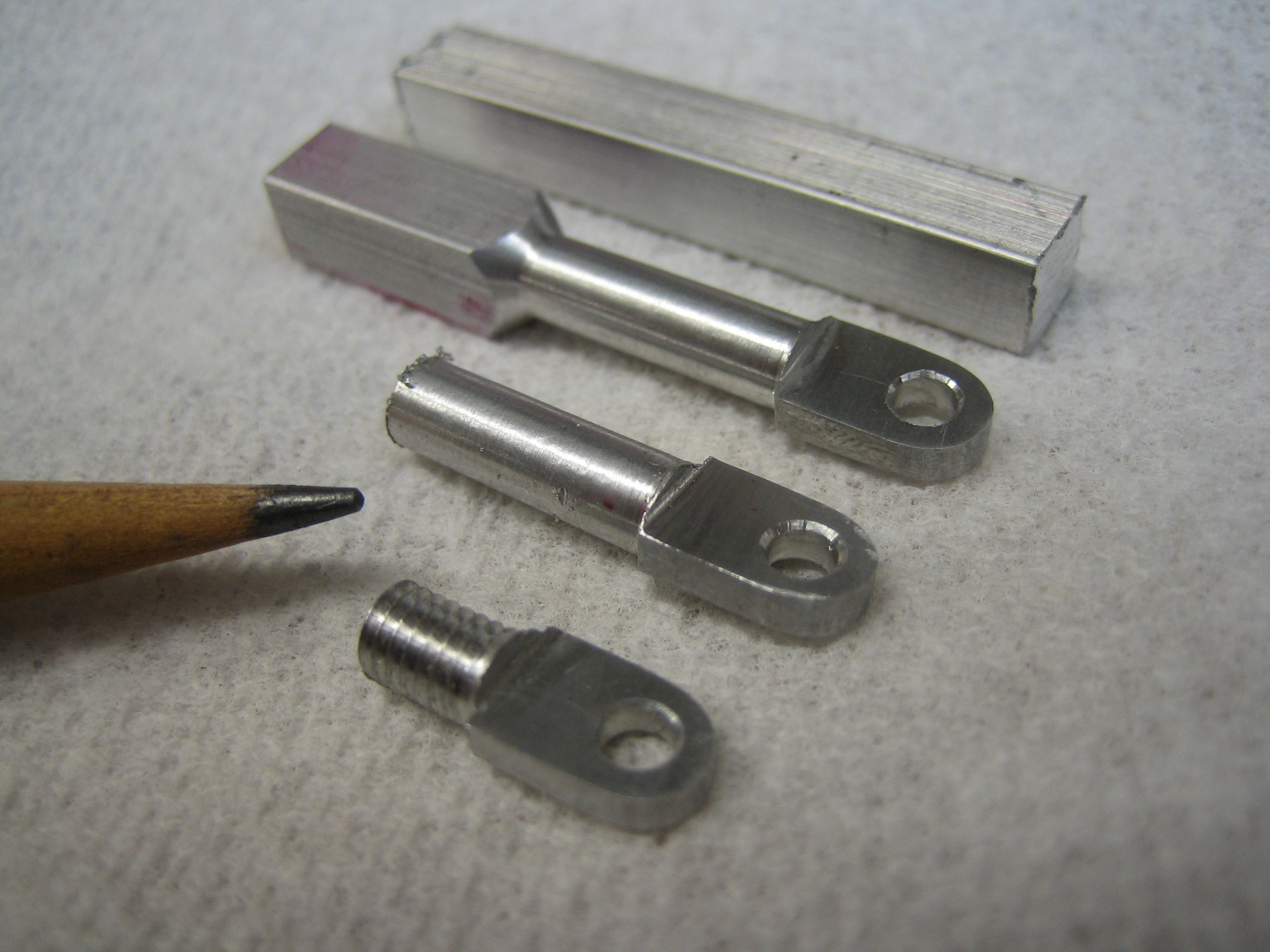
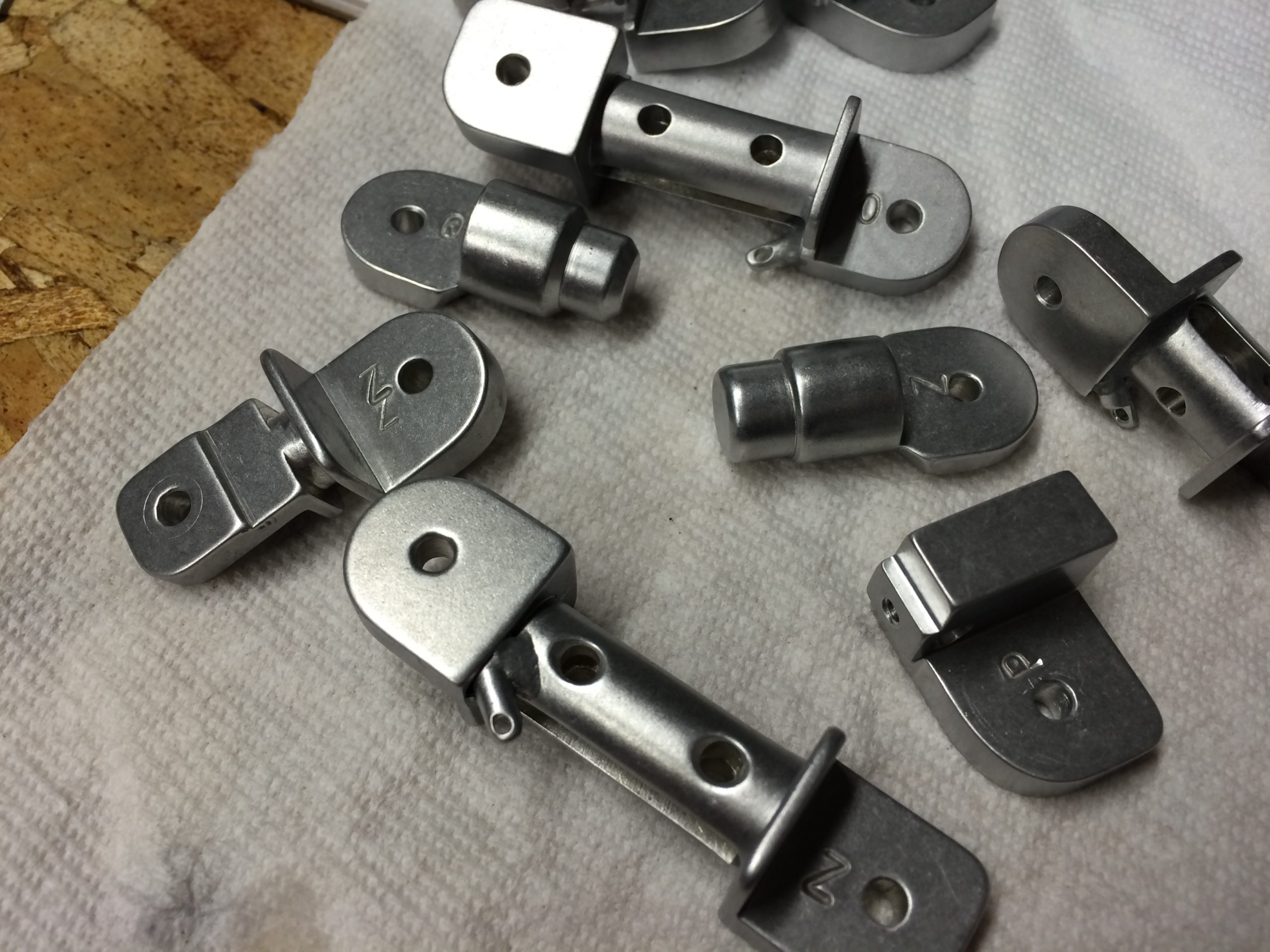
Some of the smaller parts to be made. This shows the progression from raw aluminum stock to a finished ‘lug’. This was one of several that would sever as mounting points for various ‘muscle cables’ or ‘muscle pistons’ on each of the fingers. It also involve learning about threading to make the mounting of the pieces nice and strong.
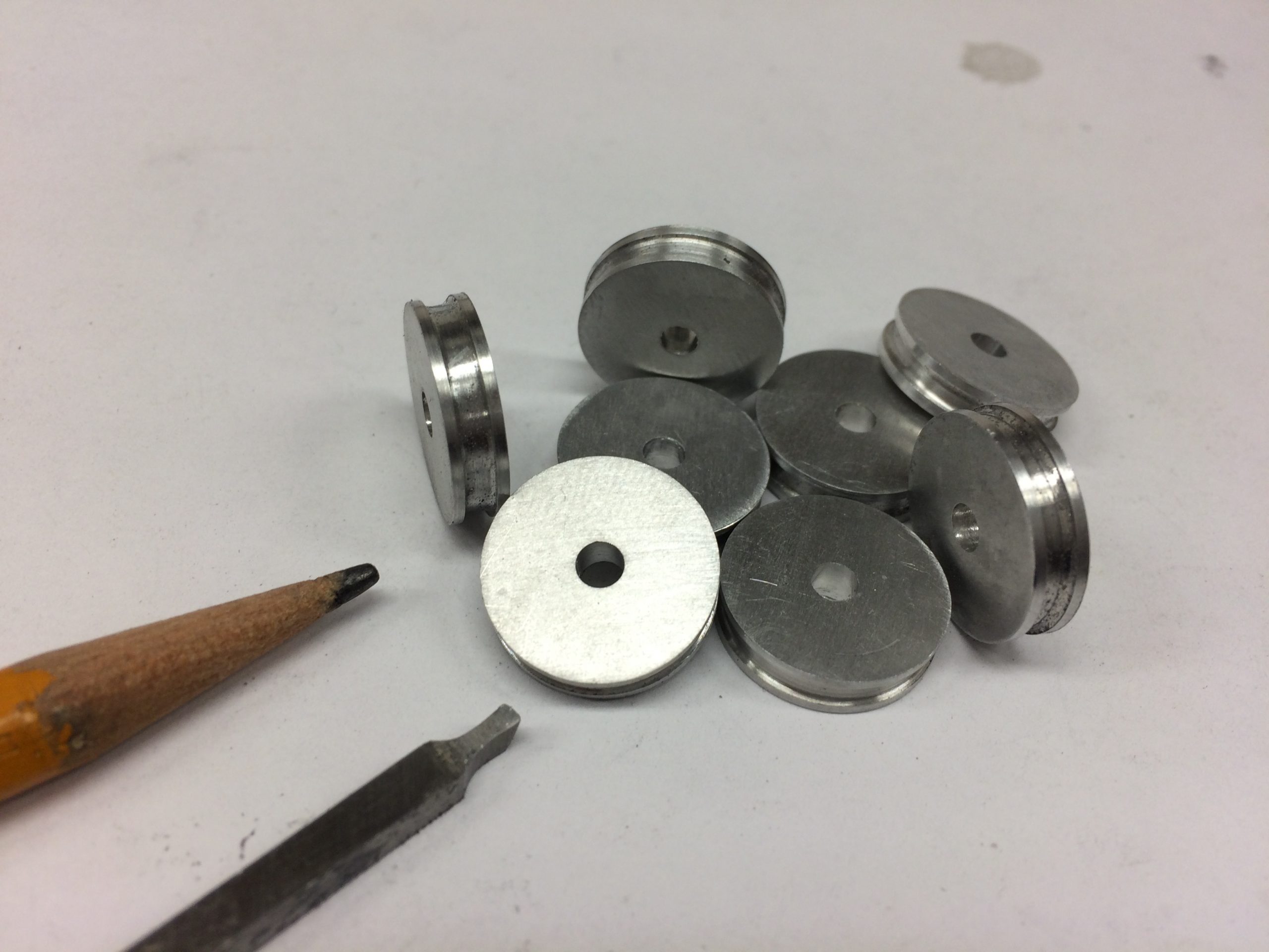
Ah, the pulleys. There were over a dozen tiny pulley required, around which all the ‘muscle cables’ would pull and flex. Since almost every one of these was a different size, I learned how to grind custom lathe tooling (the high-speed steel tool below the pencil). Another learning adventure that helped along the way.
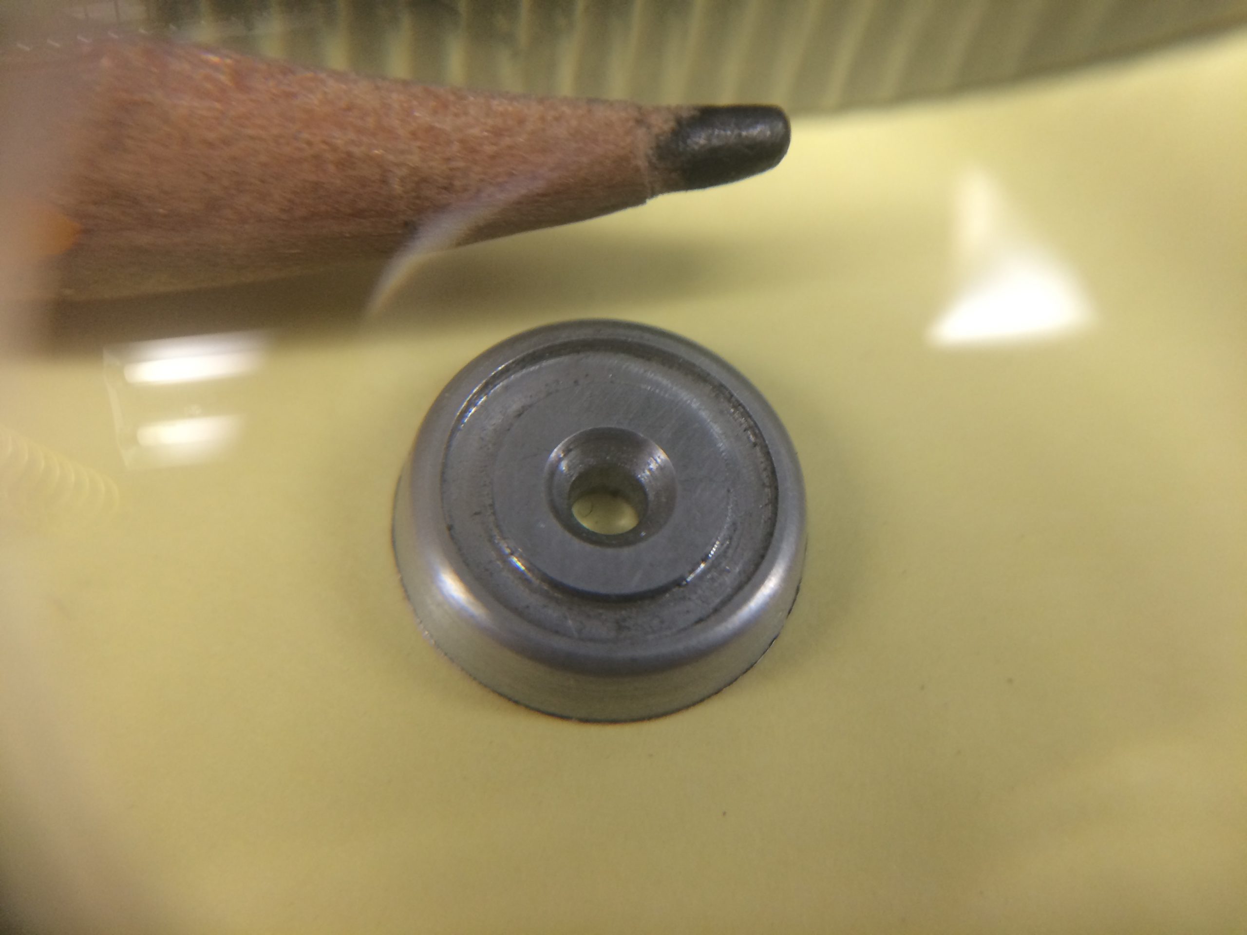
These tiny little buggers are, for lack of a better term, joint washers. Again, they each had unique shapes and dimensions so were made individually. There were around 30 on the hand and were a lot of fun getting correct on the lathe.

These little servo horns were a challenger to make. Getting the curves to all line up and deciding on the order of operations took a bit of trial and error. I’m sure an experienced machinist would had taken one look and decided on the proper course of actions but I think I wasted a few pieces after discovering I should have done things in a different order. I learn more from my mistakes than from my successes.

I owned a 30 year old Craftsman drill press. Nothing really wrong with it, but to show it some love I made a large aluminum tooling table with lots of threaded holes for jigs. I also built a digital caliper into it and mounted the table on a large X/Y Vise that I cleaned up and made more accurate. Now the drill press was a more precise tool for larger drilling projects (see the blog entry for more details). That sidetracked me for a few days, but allowed me to use my small Sherline Vise to hold some of the smaller parts. These piston shafts were about an inch and a half long. Along the way I also invested in some sets of numbered, lettered and fractional drills and reamers. Every tool I’ve bought along the way makes me think how much easier things are with the proper tools and “why did I wait so long to buy this?”. Hindsight is a powerful thing.
A bunch of axels, all drilled out and ready to be internally threaded on the lathe and cut to length for each of the various knuckle joints. I made all of these from stainless steel since they would be fit into the aluminum finger bones and might bend under too much stress. The steel being about three times stronger than the same size aluminum would have been. At about 3/16″ in diameter, they would be pretty weak if made of aluminum with the centers drilled out as they were.
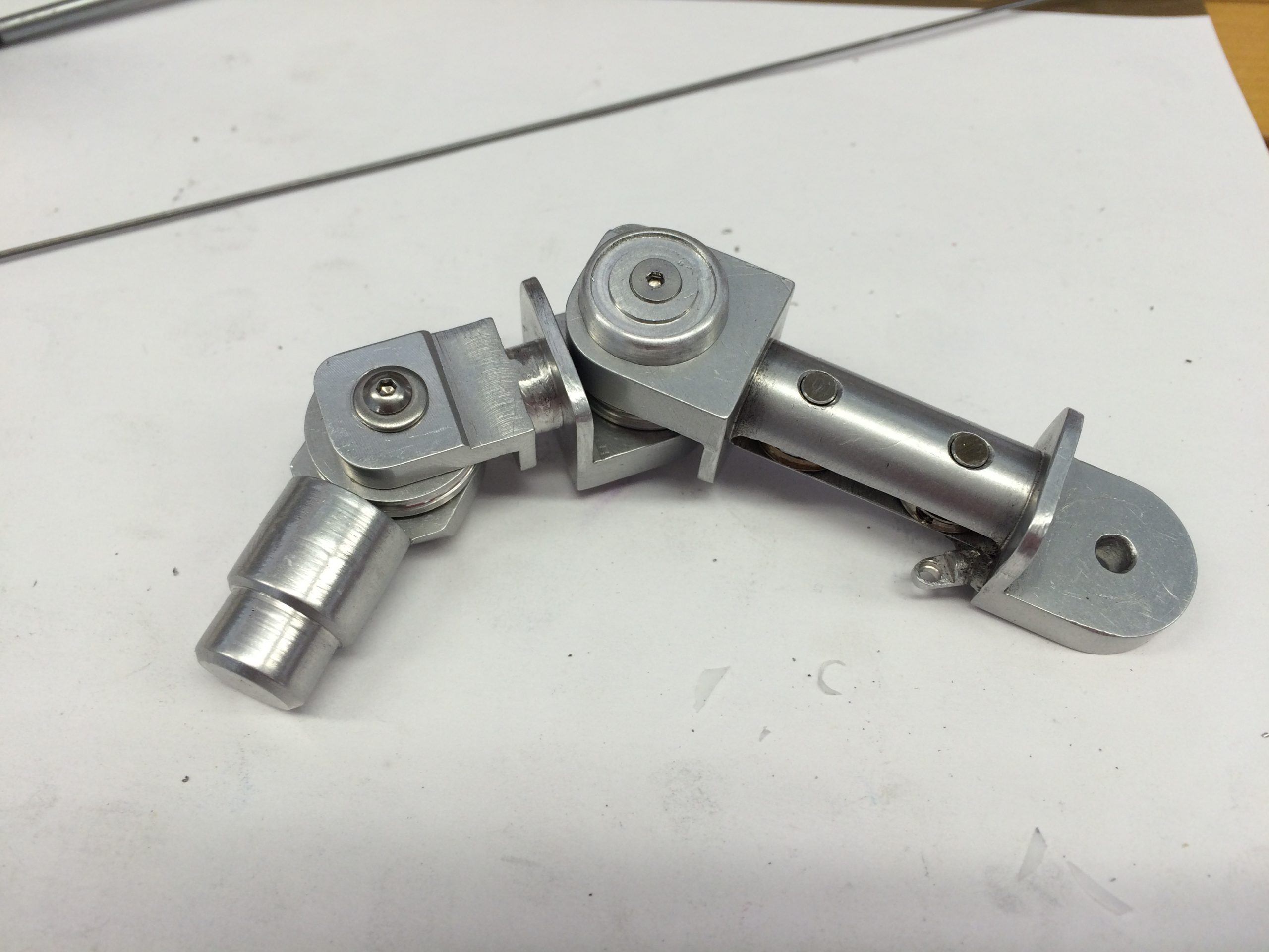
Each of the joints of the fingers relies on to things to move it. Looking at your hand, a finger can move laterally (left and right) by several degrees as well as curling up or extending. In the T800 hand, pistons loaded with springs are used to ‘push’ those movements in one direction, while ‘muscle cables’ are used to pull them in the opposite directions. Bu tightening or loosening two cables against the opposing two pistons, a finger gains a full two-axis of motion in four directions. I did a lot of searching to find stainless steel aircraft cable that was very thin, but flexible enough to go into sheathings and be ‘weaved’ around the various pulleys and joints in the fingers and hand. In the end, I purchases about six different diameters of stranded and solid cable and experimented until I like its operation. Then I made stainless steel end caps for the cables to prevent them from pulling from their lugs and cemented then with steel shavings in epoxy. I remember my grandfather used to file nails into dust then mix it into epoxy. It didn’t dawn on my what he was doing until decades later when I learned about JB Weld Epoxies.
I started to realize that it was difficult to find springs in the various diameters that I would need for the insides of the custom pistons I was making. I checked with a lot of hardware stores and someone online suggested I make my own. It had never occurred to me to make springs so I did some research into the metallurgy and heat treating process required. Turns out that many hardware stores already sell the proper steel wire (if you know exactly what you are after) and the wire is relatively cheap. That’s good because it takes some practice and trial and error. a couple hours to make a jig for my lathe so that I could wind the wires to the proper diameters.
Winding your own springs is a fascinating process to learn about. Figuring out the proper diameters and winding ‘ratios’ so that, when released, the springs are the correct size takes a lot of practice (and record keeping so you can remember how the heck you got it right once you do). It can also be an extremely dangerous endeavor, which isn’t obvious when you start. When you are winding steel cables (as in the picture above) it is easy to overlook exactly how much kinetic energy you are ‘storing’ into the metal coil. That energy is absolutely DYING to be released, and all it takes is a slip of the wire off the jig, or winding a bit too much, or forgetting tighten something properly. If that happens, that tiny piece of wire releases all the energy in an instant–causing it to rip or tear through anything nearby work that Indiana Jone’s bullwhip. Fortunately an online acquaintence with some experience with making springs warned me in advanced about this possibility. There are plenty of videos online showing how much damage a spring can do, and a lot of stories about 1/4″ springs slipping lose during creating and ripping someone’s throat out before they even knew it had happened. Armed with a healthy dose of caution, I only had a few minor mishaps for which I was a safe distance away and shielded by protective gear, but my equipment has some deep gouges from those incidents that will always be reminders for proper safety precautions.
Wrapping the springs in foil to prevent oxidation and then heat treating them in the oven at the proper temperatures and durations, then gradually cooling them for tempering took some trial and error as well but those processes are well documented in metallurgy books if you are willing to read up on it. Once removed from the oven and cooled keeping the spring oxygen free before oiling them up prevent quick flash rusting. It’s amazing how fast the steel spring would begin to turn reddish once out in the open air humidity. I learned this when lapping some of my steel pieced on wet sandpaper that they would flash rust during the summer months within minutes, so much so that I build a powered lapping table that allowed me to sand/polish metal underwater (see another blog entry on my shop pages for details). This had two benefits: The water continuously running over the parts as I lapped them washed away the grit and particles, preventing scratching an ‘lubricating’ the lapping, and the water kept the oxygen in our humid air from flash rusting the part in less than a minute. Once I removed items from the water I would immediately dry and clean them in acetone to remove any contaminents and apply one of either oil or wax depending on the part and its use. Camilia Oil is a favorite of mine for preventing was on steel tools that are exposed to air.
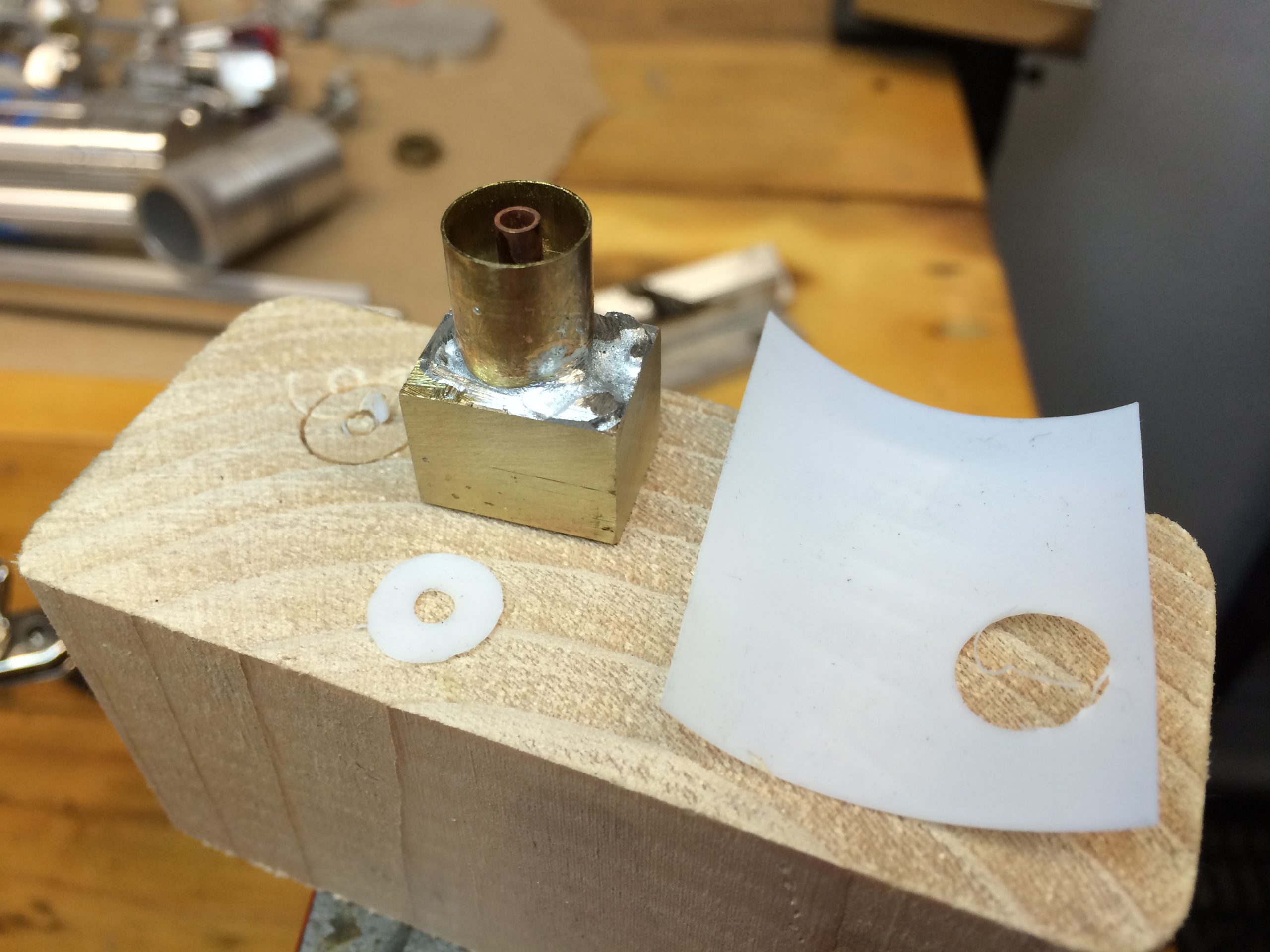
All those aluminum knucke joints rubbing against each other would scratch my finely polished pieces over time. I was thinking of making some thin bronze or brass washers but that would add up to visible gaps between the pieces that would differ from the original arm’s design too much for me to tolerate. So I came up with the idea of using very thin sheets of Teflon. Hey, if it is friction and stick resistant enough for your pots and pans, it’s good enough for the Terminator, right? After learning how difficult it is to hand-cut tine circles by hand I soldered up a small ‘punch’ from some brass tubing and block and sharpened the edges. Now I could would wack the press through the teflon sheet into a soft pice of pine and crank out several dozen tiny Teflon washers in a few minutes.
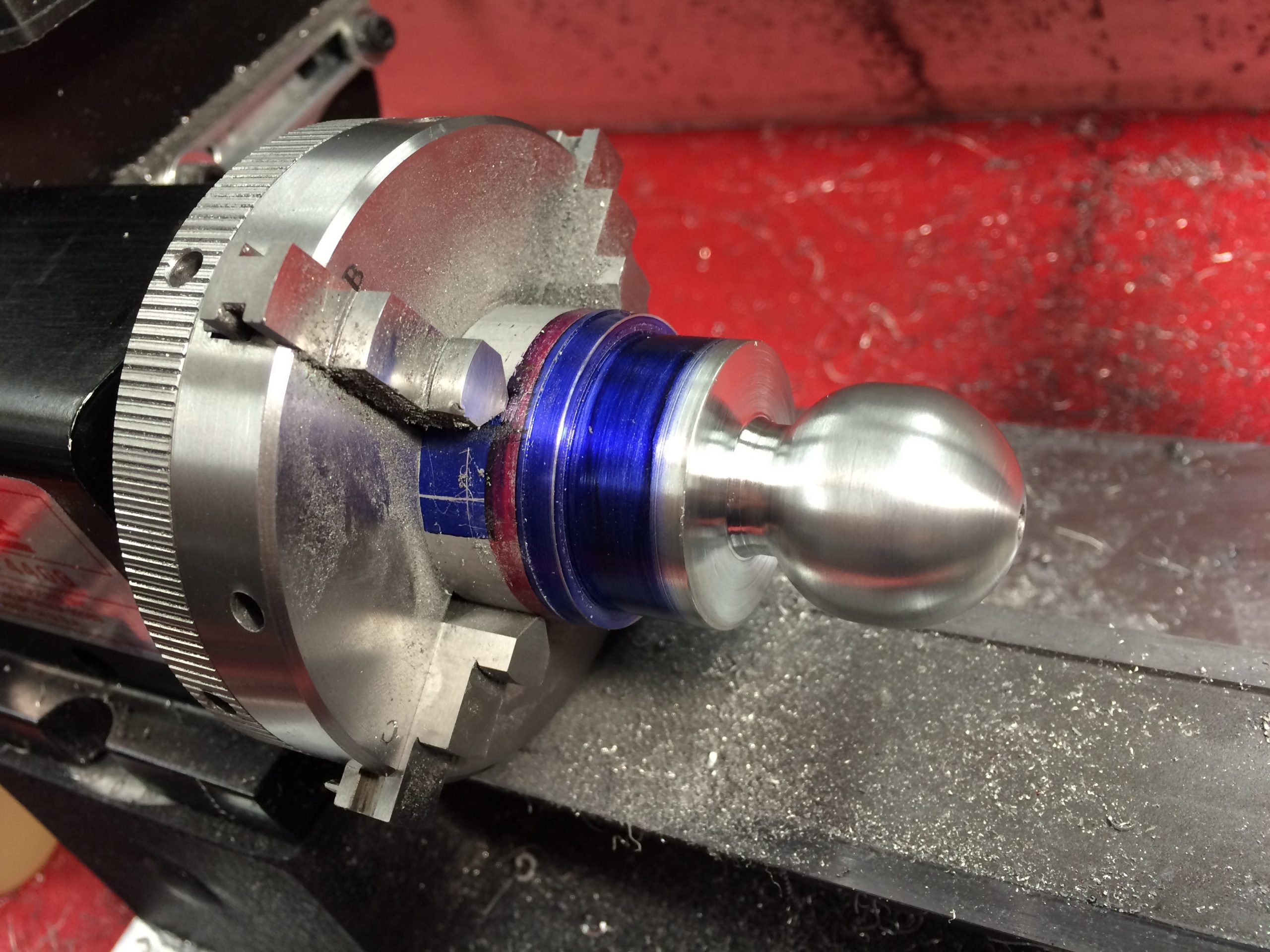
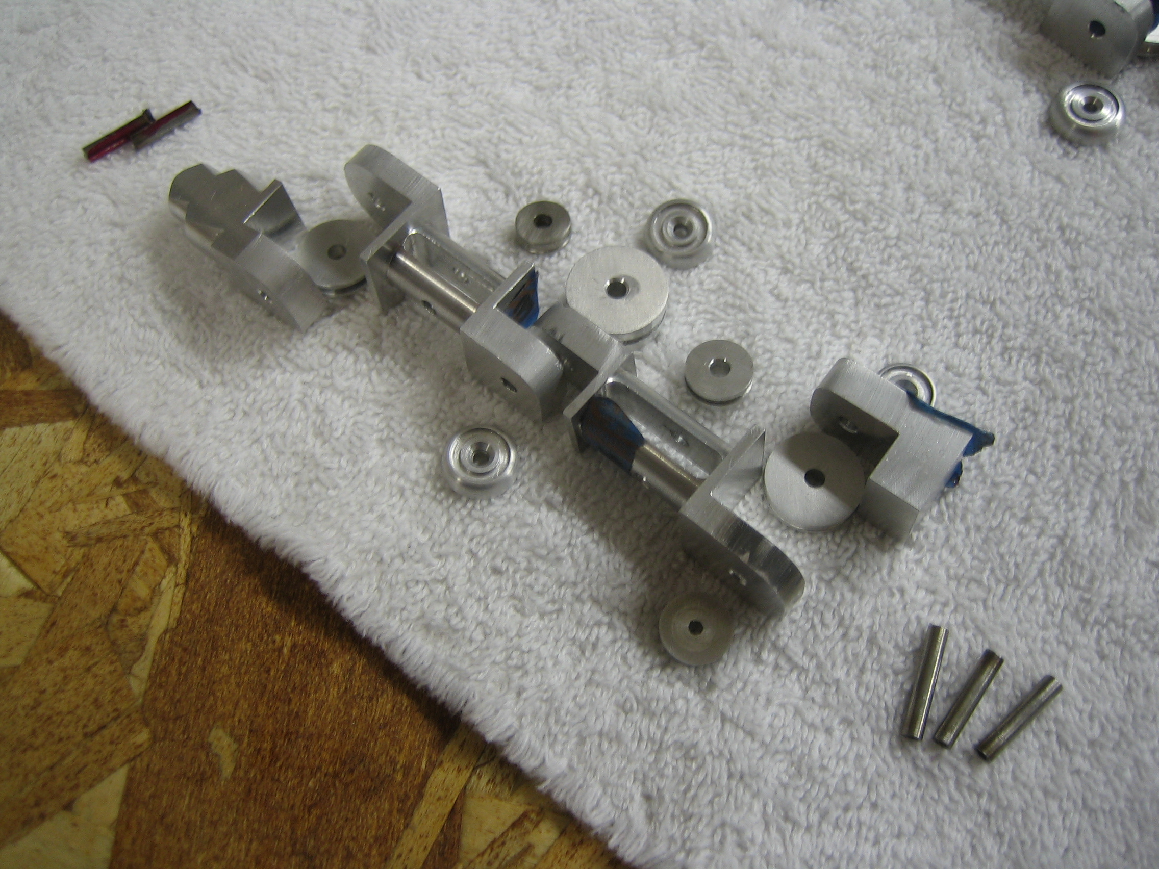
The wrist ball being turned on the lathe. Not having a true ball turning jig, I cut incremental notches to get the ball close to shape, then used files followed by progressively finer grits of wet sandpaper with aluminum cutting fluid. A final polish wrapped it up nicely.
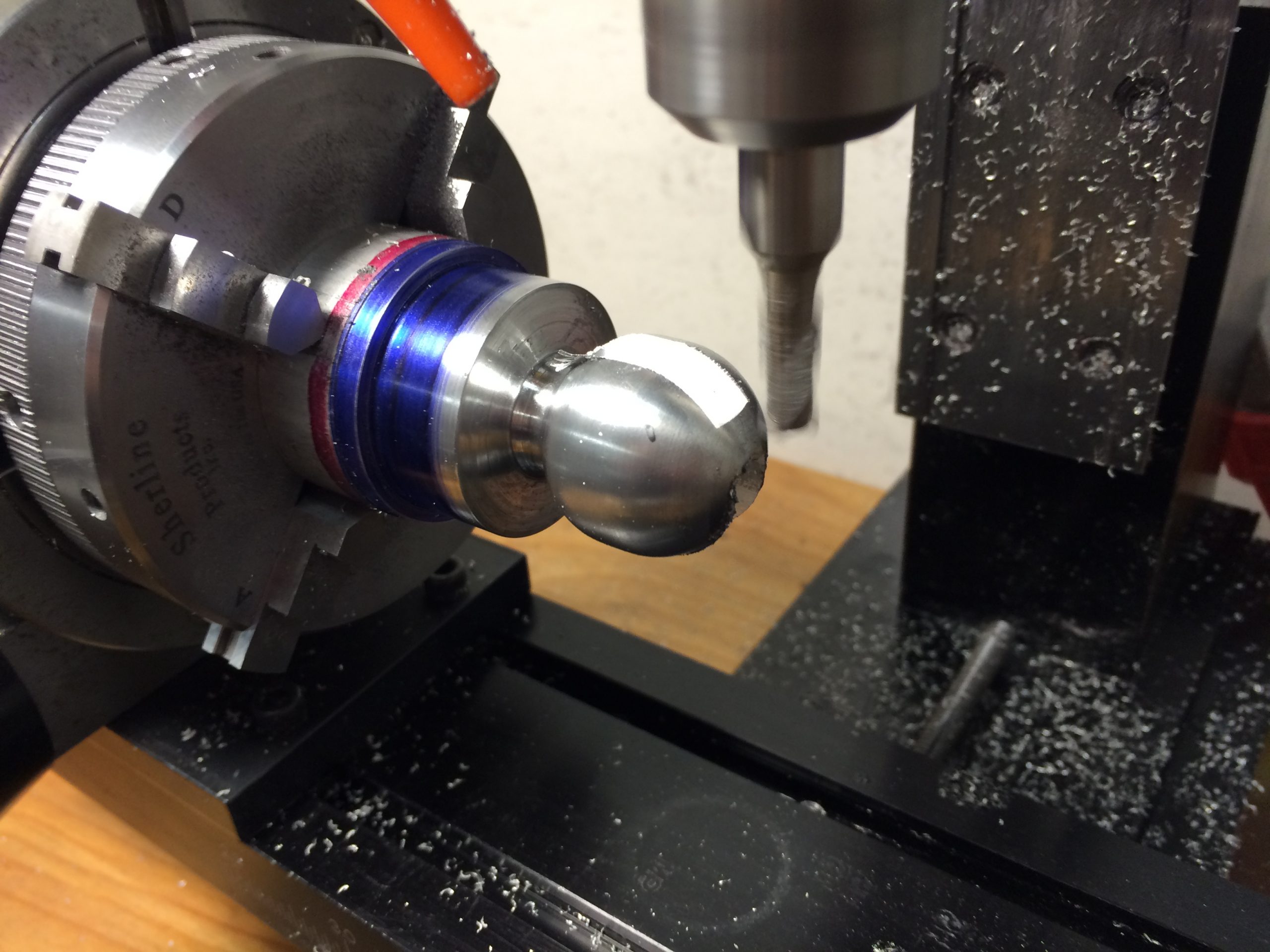
Transferring the chuck with the ball joint over to my mill, I used a slotting end mill to carve out the slots for the pin that would align and allow a full range of motion.
Three smaller ball joints would be needed for the three main forearm pistons. These were bolted to the bottom of the wrist plate. Movement of those three spring loaded pistons cause the motion of the ball joint in the wrist allowing it to be quite flexible. These, like most of the pieces in the wrist were made from aluminum.

The final pieces of the wrist joint freshly cut and awaiting tumbling and polish. At the top of the image is the ‘head’ of the wrist ‘bone’. The original was most likely make from a small unidentified piston so I duplicated the measurements I took from various photos to get the scale of all the details. The curves were cut similarly to the forearm casing using my Pathfinder application to generate the final code for the rotary table on my mill.
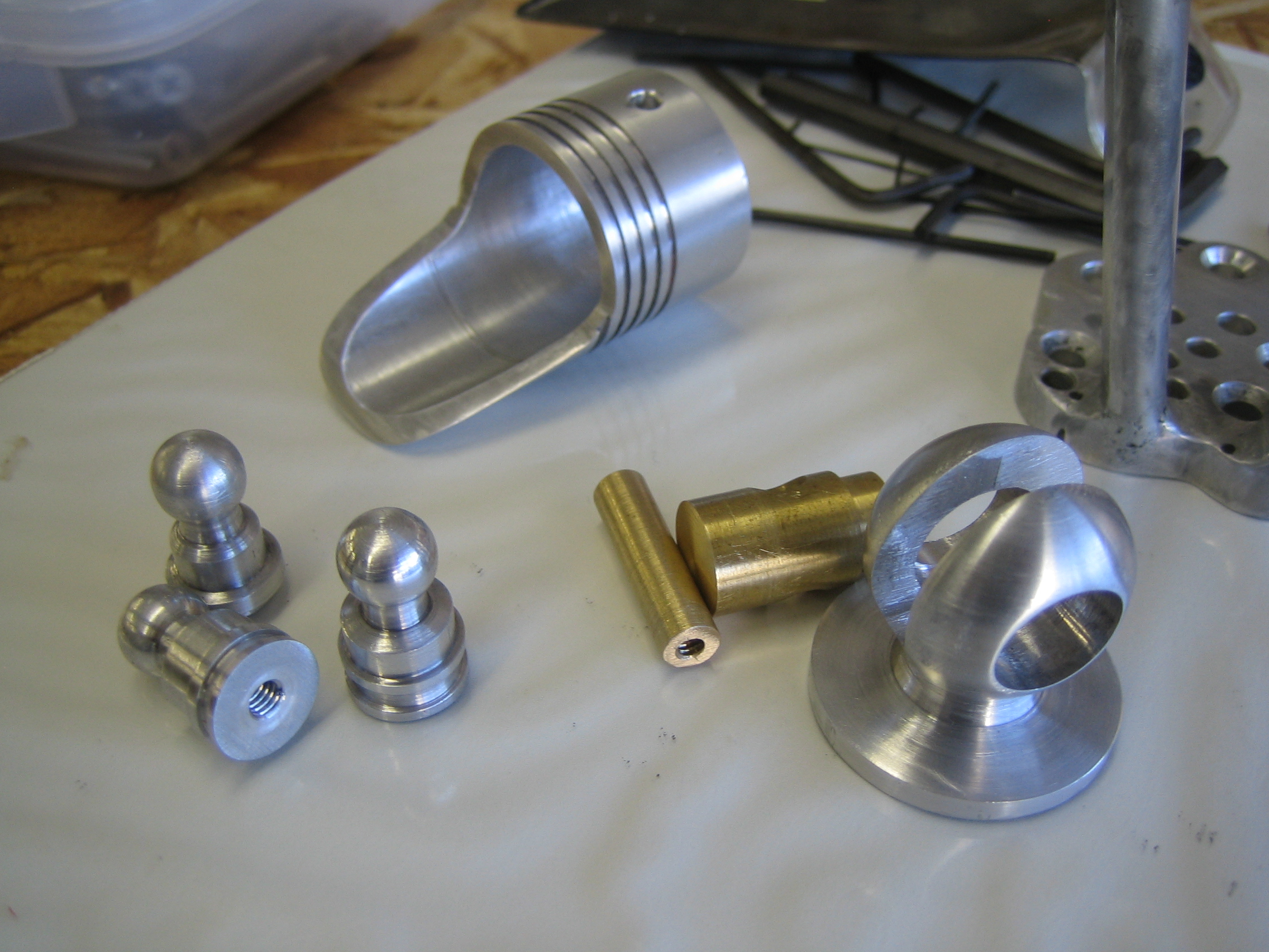
The final wrist ball joint. The stainless steel pin allow movement laterally while the ball allows full rotation. A turned bronze center socket piece holds everything together and reduces any friction.
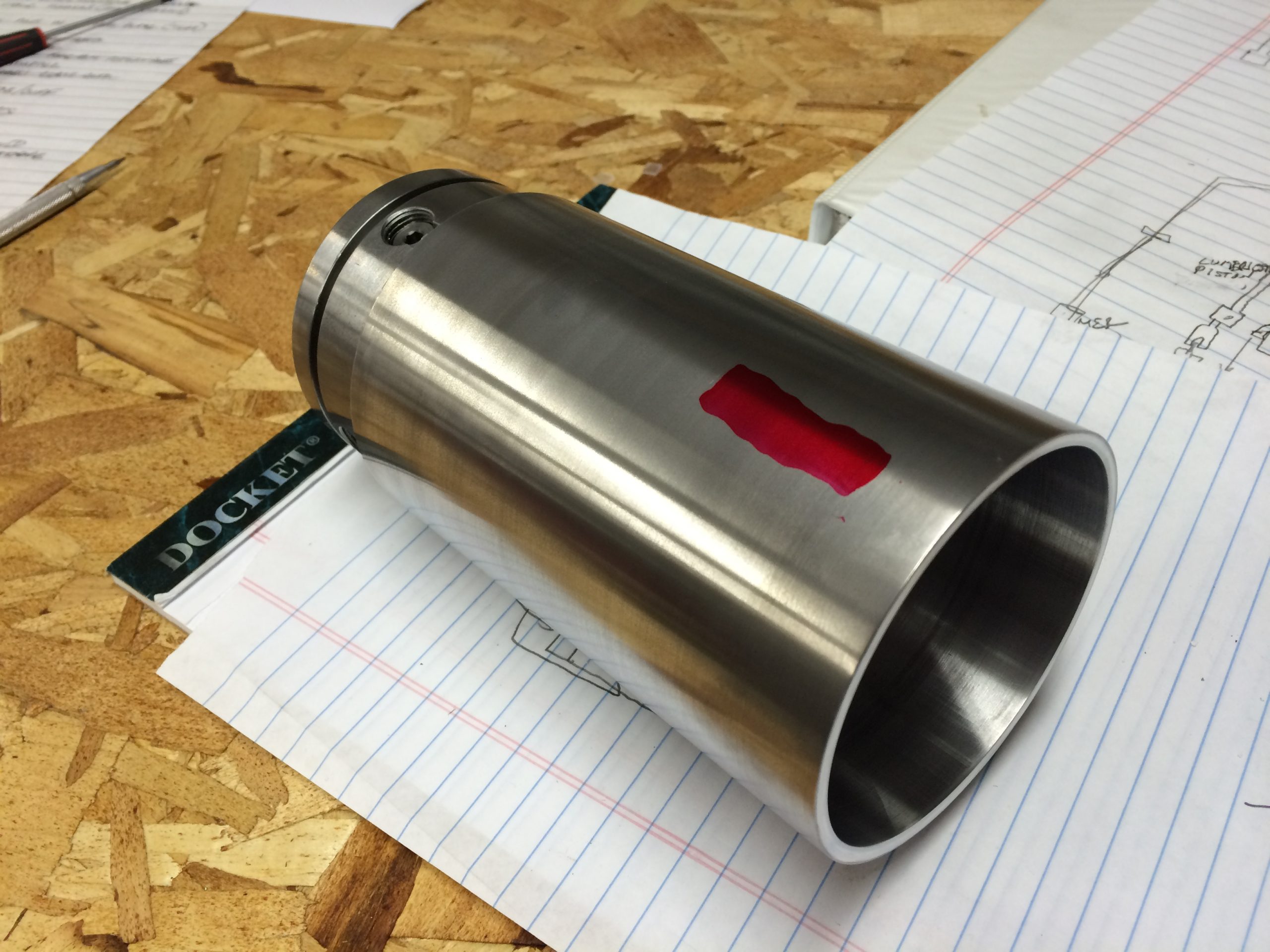
An thick aluminum tube would server and the foundation of the forearm and main ‘load-bearing’ element.
The forearm ‘ulna/radius’ bone was originally made from what appeared to be a hollow piston, cut and machined into the final shapes. I duplicated this from some aluminum tubing and machined it to shape on my mill and lathe. The wrist joint, a kind of combined two-axis joint mimicking the Scaphoid and Lunate bones of you wrist, was a couplex ball joint. I machined it from a two inch cylinder of aluminum, machining the ball and hollowing out the center for a bronze ‘axle’ for the fore/aft movement of the wrist. The ball action allowed for full rotation and lateral movement very similar to a real human wrist. This was a challenging piece to get accurate within it’s socket.
Having had a background in graphic commercial arts and spent a lot of time drawing the human figure, I had learned a lot of human anatomy. So keeping all the parts straight by their ‘human counterpart’ names became second nature. These muscle piston bases are a mix of your forearm flexors and extensors, controlling the movements of the wrist more then the elbow in the case of the Terminator’s arm. These would have large springs inside as ‘pushers’ against the pistons that they would contain, holding the wrist in a default position, but allowing it to be move about in any direction.
More tiny lugs awaiting cleanup and polishing before being attached to pistons.

The forearm ‘shell’ was one of the largest pieces of the arm and really forced me to be creative when working within the smaller size envelope of my precision machining tools. Cutting up the large aluminum tube that would be used required a large wooden jib for my newly restored metal cutting bandsaw.
The forearm casing has a lot of precise detailing carved into the surfaces and a curved profile shape. It was too large for my lathe, so after the initial cutting and polishing of the tube, I held it in place with my rotary table’s chuck with the jaws reversed as to hold it from the inside of the tube.

This would be a little precarious. Since the part was nearly four inches in diameter and several inches long, common sense told me that it really should be held tightly at both ends. Unfortunately I couldn’t come up with a good method with the tooling I possessed. Instead I decided to proceed very slowly and with very shallow depth of cut for all the operations on this piece as to not dislodge it from the chuck on the one end, nor make it displace and ruin all the work as it drifted off course.
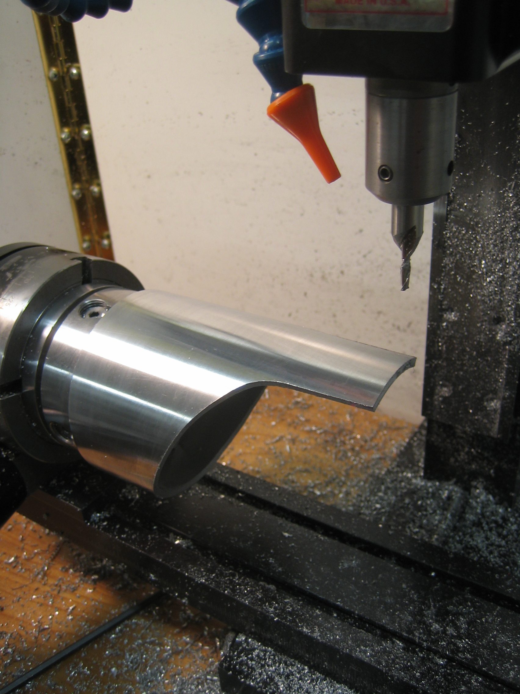
I used some aluminum cutting lubricant and lots of compressed air to keep the chips clean. That, combines with nice a slow, shallow cuts worked very well. The complex curves were calculated with the Pathfinder curve cutting application I had written and I nailed it on the first try using a 1/8″ two fluted end mill on my mill. Mounting the rotary table with the chuck and workpiece at the very end of the mill’s X-axis gave me just barely enough room. If the piece had been an inch longer I wouldn’t have been able to do it.
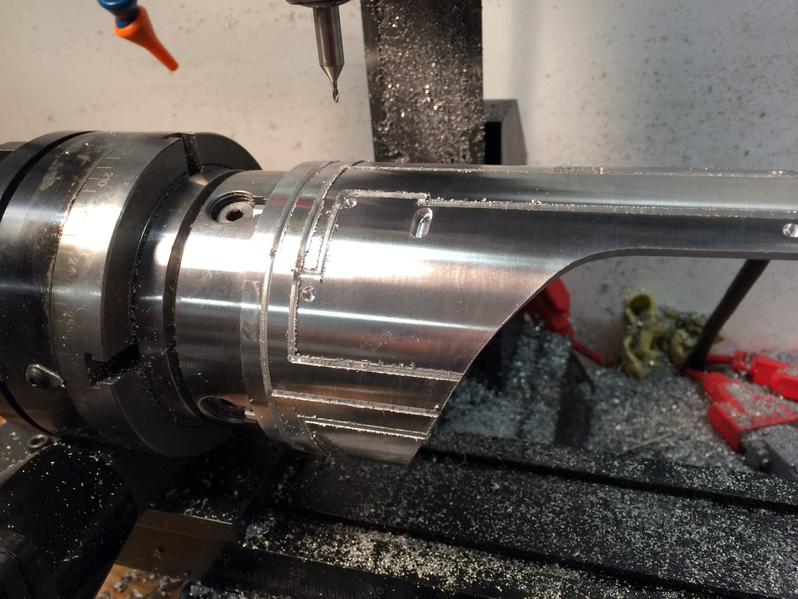
I designed the rest of the etched details in my Milldroid application and again, used slow, shallow depth of cuts to machine out the rest of the slotted details into the surface of the forearm shell.
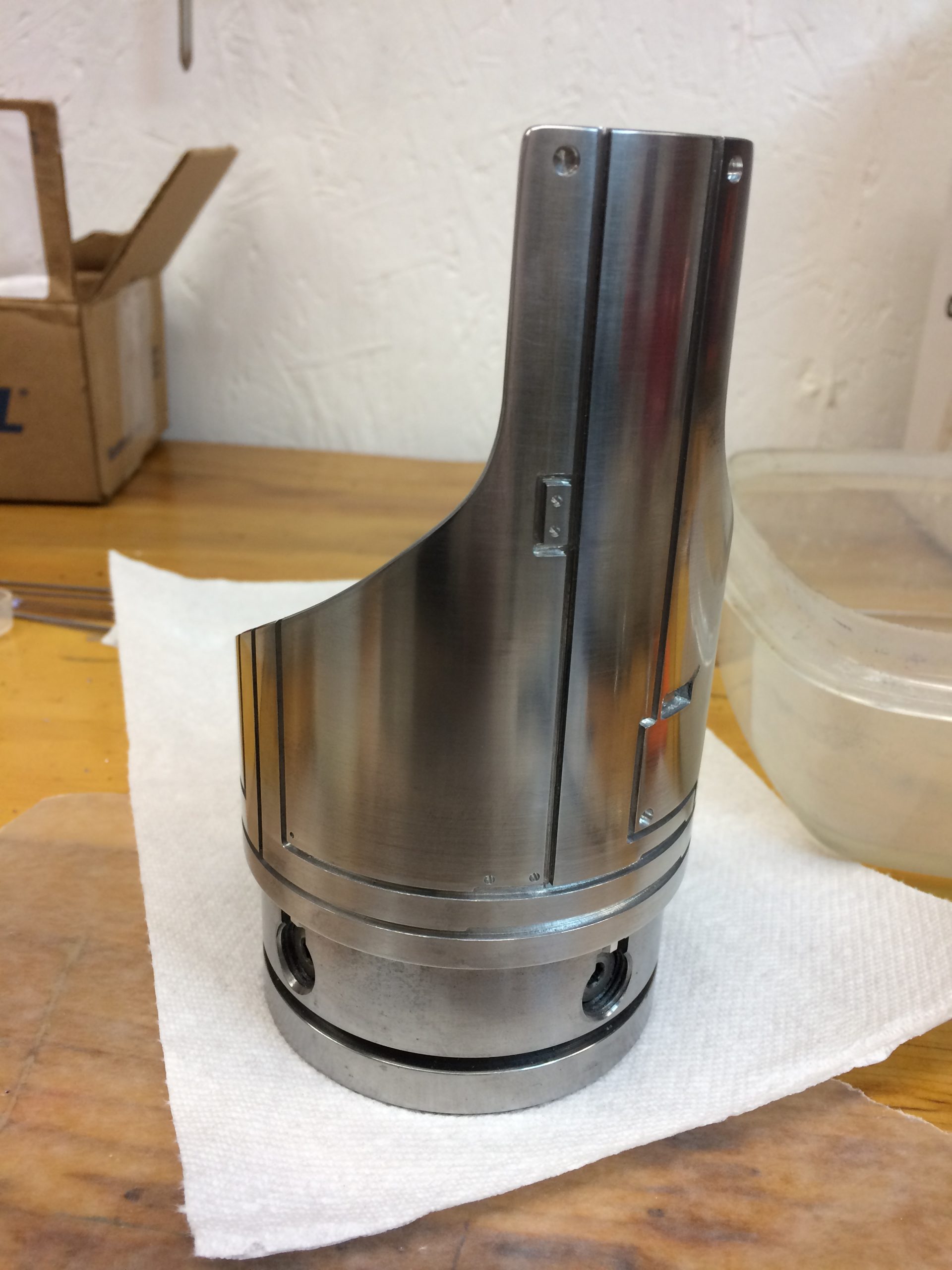
The final result. I was very pleased with it, not to mention a bit surprised that I only had to make one. I because of the large nature of the part I feel certain it would take two or three before I got it perfect.
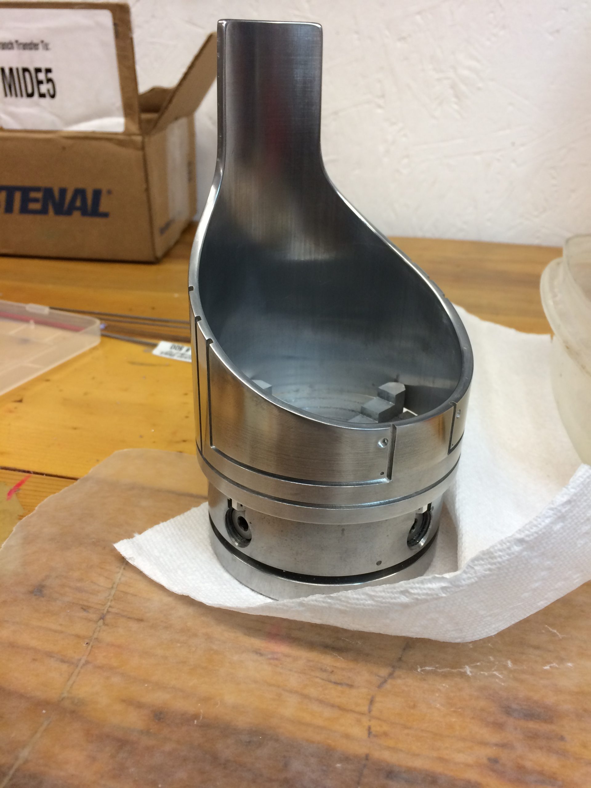
The final shell, after some minor demurring, was polished with various reducing grits of aluminum wet and paper and aluminum polishing compounds to achieve a nice shine.
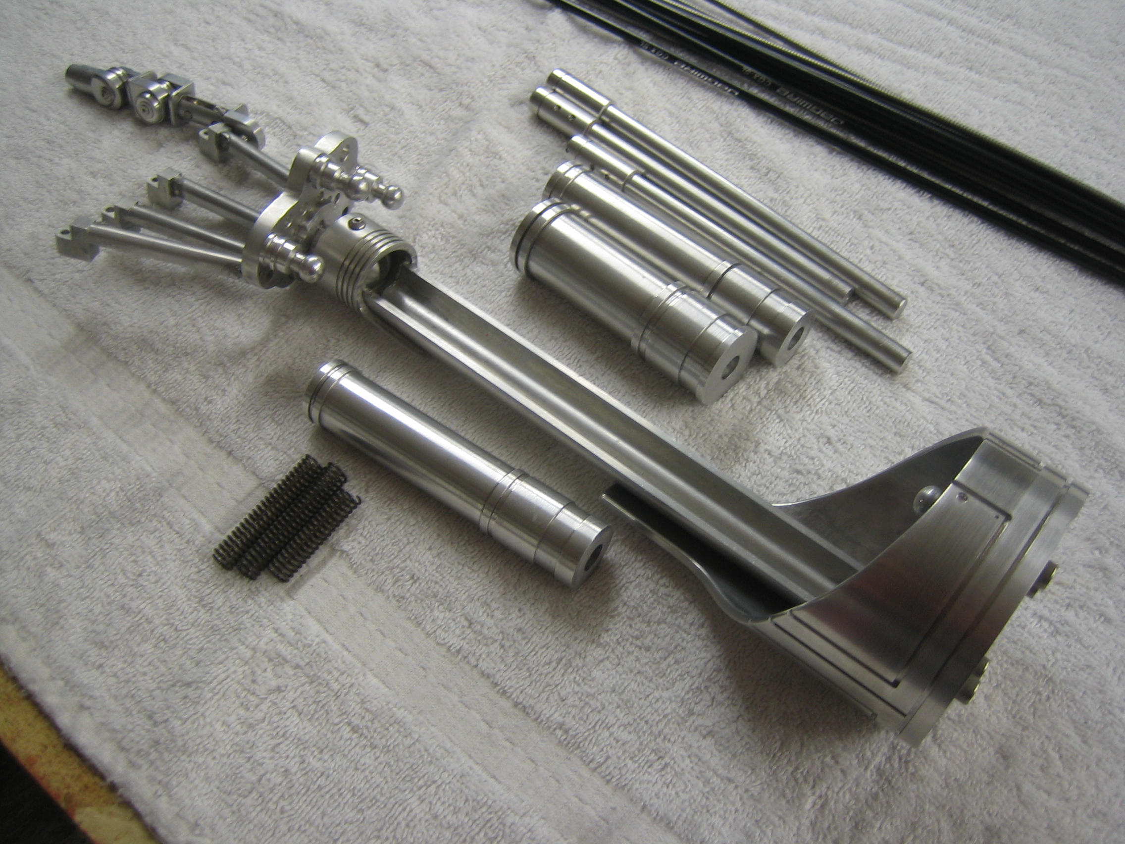
Here are some of the forearm pieces being test fitted to some of the hand elements. Better to know it is all going to fit together BEFORE I complete all the other parts, right?
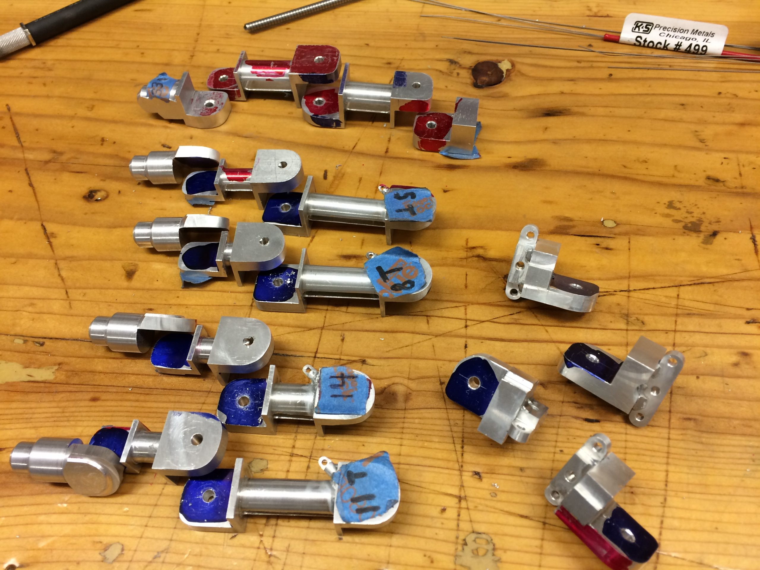
Now that I have the processes down pat for fingers I could go back and start cranking out all the different phalanges. Almost every one of the bones in the hand is different enough to require individual machining. As I started losing track of which was which I had to come up with a labeling system for the parts, hence the tape labels and some of the dykem dye choice on the parts. The dyes helped me keep track of which surface still needed flycutting for maximum accuracy.
This give a good indication of the complexity involved in a single finger. These are all the parts, each custom made from washers to axels, in the index finger. Still missing from this photo are the custom springs, pistons and cabling. Approximately 30-35 parts per finger total.

It’s starting to look like a hand now. The main phalanges and metacarpals, lugs and fingertips ready for tumbling and polishing.
The first finger test assembled. The single Phillips screw and Cap Screws are the only parts that weren’t custom made. I used an off the shelf stainless screw for those of the same exact part used in the original arm. If it hadn’t been off the shelf on the original, you can bet I would have made them from scratch too. The fingertip on this one ended up being remade, as the surface finish was a little rough for my approval.
Some phalanges after coming out of the tumbling process. I used some small tumbler media of pyramids, just large enough to not get into the holes and damage the precise diameters I has drilled and reamed for the axels. After the pyramid media, I went with a finer media of ‘lizard bedding” from a pet store. This is a duplicate of tumbler media that you find for 1/10th the cost and is the same exact material. Thanks to some online experts who informed me about cheaper sources for tumbler media–that save a lot of money. The final tumbling was mixed with some red rough polishing compound that gave me this final rich luster. The final pieces transformed form an aluminum luster to an almost nickel-like sheen.