The final arm in it’s display case home. Several hundred parts in total and almost two years from conception to completion. In addition to the arm, I built and completed my wood and metal shop and gained quite a few new tools. I also restored quite a few as well, and every one was a learning experience. I also wrote quite a bit of custom software for the mill, lathe, and other items for the shop. I’m mighty proud of what I created and learned along the way considering that when I started I had few metal-working tools beyond a hacksaw.
Originally I planned to make a display case identical to the one that Miles Dyson admires in the vault Terminator 2. It looked as though it had been made from metal and glass, but I was unable to machine a large enough piece of metal to match it for the base, so I decided to go with wood and plexiglass.
Some 1/8″ and 1/4′ plywood would serve as the foundations for the base and lid. Plywood ribs added some structural stability to the cylinder-like top and bottom.
Epoxy was used to glue all the wooded ribs and rings into the rough shape.
Once the top and bottom cores had dried, I wrapped both pieces with 1/64″ plywood bent to the cylindrical shape. Again, epoxy was used to hold this skin onto the ribs.
After some sanding, I used wood filler to fill in any large gaps and seams.
Hardware of blind nuts was epoxied into place and then reinforced with plywood. Then the entire interior was reinforced with fiberglass cloth and epoxy for strength. This gave the once-flimsy 1/64″ outer plywood skin a metal-like solidity.
There were actually four wooden pieces to the case: From left to right the base, the shoulder for the top, the shoulder for the bottom with holes for the arm cabling and the top. The smaller holes in the shoulders are for 10 small LED spotlights that would iluminate the arm from within the case.
I decided to engrave a nameplate for the arm using my mill and some engraving bits. Once again, my MillDroid software provided the layout and CNC control.
I purchased a 10-inch diameter, 36″ length of 1/4″ plexiglass tubing. After a few practice cuts I fire-glazed the edges to get a clean edge. This is when I goofed–I overheated the edge, and caused one end of the tube to shrink by about a 1/4″ in the overall diameter. It affects the outer three inches of the tube, ruining the piece and forcing me to purchase a second tube and start over. I was much more cautious and the second tube came out perfect. It was a $60 mistake that bought me how quickly the heat of a torch can melt expensive plastics.
The two shoulder pieces are now painted and mounted to the top and bottom of the case. The finished wood pieces were finished with several coats of thinned wood filler, sanding sealer, then shellac with lots of fine sanding between each. A couple coats of enamel primer and three coats of nickel satin paint then three coats of satin clear coat. The shoulders where then wrapped with a 1/16″ inch layer of gray hard foam. This brought the shoulder diameter up to just slightly larger than the inner diameter of the plexiglass tube for a snug slip fit.
The case awaiting interior detailing and wiring. On the right you can see the $60 mistake I made on the first tube attempt. Ugh. Hope to find a use for is someday.
I didn’t take any pictures of the interior wiring. It consisted of a couple of 1/8″ power jacks (one for the top and once for the bottom) and some small LED “Projectors” that I machined from styrene and metal to emulate the look of the arm’s mechanics. I alternated blue and white LEDs to get a nice lighting arrangement on the metal of the arm.
Assembly was hardly a start-to-finish process. I would test fit a group of pieces, say of a single finger, then pull it all apart and make adjustments. Something this was a bit of filing to make an axle a bit smoother. Sometimes it would involve polishing a piece a bit more or removing some burrs that were missing during finishing or tumbling. On average I would guess that everything was assembled at least 3-5 times each before dismantling it all before final assembly. I then literally ‘dunked’ all the pieces into an aluminum protective coating to prevent oxidation. Stainless steel parts were similarly protected by oiling or teflon lubricants. After a couple days hanging and drying final assembly could begin.
I used my Panavise to hold the palm plate and began attaching the skeletally completed fingers to the metacarpals. A bit of finessing for a good fit was necessary for each joint along with proper lubrication and remembering to add all the teflon washers I has made to reduce friction. If I had not been so concerned with matching the original arm construction, I would have probably made a change regarding the joints of all the moving parts. As they were originally made, the tightness of the cap screws of each joint determines how tight the joint actually is for movement–this is fundamentally a bad design and why I had to make certain I didn’t over-tighten the joints and bend the metal pieces and cause too much friction. A better design would have been to make some bronze or brass bearing sleeves for the interior of each joint that would prevent over tightening. As it was, I relied on red loc-tite for hold all the cap screws in their permanent positions and thus remained true to matching the original look.
More fingers being mounted, the thumb and all the interior pulleys awaiting cabling. The thumb pivots around the base of the wrist plate, consisting of a cable (for tightening the thumb joints) and a rotating sleeve around the cable (for rotation of the thumb). The orinal props thumb has some design limitations over a real thumb, but accuracy was everything for this project.
I used some tiny paint brushes to apply teflon lubricant and loc-tite where necessary. The areas for application were too small to get into with the bottles and applicators. I avoided silicone lubrication so I would not have any contamination issues with the aluminum protective finishes. Once you get silicone onto a project, it is almost impossible to clean it off short of scrubbing and soaking the part in acetone. Better to keep it out of the shop entirely unless absolutely necessary.
Muscle cables and sheaths being installed. I spent a good amount of time looking for stainless steel cabling stranded cabling that was strong enough and flexible enough to bend around the joints and pulleys yet look the proper diameter of that in the film. It turned out to be an impossible task for a couple of reasons. Cable that looked thick enough in the closeups of the arm could not have been flexible enough to use in the ‘moving arm’ that flexes at the end of Arnold’s arm in some scenes. The conclusion was that the two different scenes had two different props. Since I wanted visual accuracy over movability, I chose the thicker of the cabling choices. The joints could still be pulled and released somewhat, but it would never be as ‘animatable’ as the motion prop that was used in that scene. The sheathes for the cable tool nearly as long to locate. I found a company that made the sheaths for mountain bike brake cables that were encased in rubber. Underneath, they were a nice stainless steel (to help avoid rust) and looked perfect. Some interior lube and threading of the cables and I had my “muscles” ready to be threaded in and around all the pulleys’.
Ajusting the tension on the cables against the springs that were in all the pistons to achieve a nice ‘balanced’ look and feel took some tweaking, but it was really satisfying to be able to pull a cable from in the base of the forearm and finally see a finger flex and pivot. At this point it was starting to feel like a completed project.
A closeup of the fingertips
Here you can see the dual sheaths for controlling each finger at their bases. In this photo the cables are not yet threaded through the sheaths and pulleys, nor are the ‘palmer pistons’ installed on the empty lugs that would pull each finger down.
A closeup of the wrist plate, showing the three smaller ball joints at the end of the forearm pistons. The palmer piston are in place here, pushing against the palm to straighten each finger. All the finger cable sheaths continue down through the wrist plate and through the forearm to the elbow region. As the cable sheaths began to multiple I worried that the amount of parts in the forearm would be too dense to be contained in the allotted space and still allow movement and ‘good looks’. In the end it all fit. Barely.
Trying to crawl away towards Sarah Conner, methinks.
Here you can see some of the detail on the back of the hand and the side pistons for each finger. These spring-loaded pistons, along with a counter cable/sheath on the opposite side, cause the lateral side-to-side movement of each finger, similar to you you cam spread your singers apart.
Details of the base of each finger. The lateral cabling is not attached in this shot and one of the sheaths is not attached.
Details of the palmer pistons mounted to the lugs on each finger to push them into their straight positions. Cabling is present in this image.
Closeup of all the cable sheaths in place. You can see where, along with all the pistons, the area at the base of the wrist plate becomes quite congested with moving parts.
Forearm showing the three large pistons and ball joints for pivoting wrist movement. Lots of tiny set screws visible for adjusting and locking the springs and ball joint pieces in place.
As I generated more parts, the sheer number of pieces became difficult to track. While I could stamp some larger piece with alphanumeric stamps and a hammer for later identification, tiny pieces were more difficult to identify. Combined with the fact that some tiny parts existed as ten to twenty pieces that might look identical but have slightly different measurements each. Many times I would set something down, then need to come back and re-measure fifteen or twenty pieces to find the one I had misplaced. I started a ‘bagging’ system of tiny kitchen zip-lock bags, labeling them similarly until I had enough parts to group entire sections such as “index finger” or “thumb. After that I reorganized everything be group for final assembly.
The first ‘pass’ of organization into similar parts. The labels read like the table of contents of “Gray’s Anatomy” Volume 1.
As all the parts for individual fingers were completed, those associated parts could be unbaked and placed together.
At this point, smaller threaded parts could be made and cut to final lengths during test fittings. The tiny little pieces as set screws, as small as #2-64 size, which were quite the challenge to cut to length and then correct any threads that were ‘spoiled’ in the cutting process. I used a tiny set of jeweler’s files under a microscope for that work and made my own set of tiny hex drivers (because I was practicing knurling at the time) to work them. Springs could now be cut to size, having been made long in case of mistakes.
Forearm parts all being inventoried with the larger piston springs being adjusted for size. Small set screws for these would let me lock springs into proper position and allow for adjustment for proper tension.
Wrist, forearm and ‘elbow plate’ and associated parts after cleanup and organization.
A couple of fingers and their pulley, pins, end caps, teflon washers and phalanges.
From a distance it I sometimes can’t believe I kept it all straight for the duration of the project.
So at this point I basically started over, having learned from my mistakes. I had finished assembly a complete finger as a prototype and felt confident I could machine all the rest of the parts. over the course of the next several months I did just that, refining my ‘MillDroid’ CNC software and building new tools along the way. Here are some of the highlights along the journey….
Without the ability to weld aluminum, sometimes I wasted a lot of metal. The carpals and metacarpals of the hand would have probably been more efficient to machine from separate pieces, but I pushed everything through as a single pice of metal whenever possible for strength and ease of assembly later.
Pieces such as this, while difficult to machine, were much stronger that if they have been separate pieces held together with a screw. Plus, being true to the original arm prop, if I didn’t see a screw holding it, that meant I tried my best to machine it as the original was, no matter how difficult.
I did do a very small amount of aluminum soldering. I was never happy about the strength of these joints, but again, wanted to stay true to the original.
The ‘palm plate’ or metacarpal plate served as the base of the hand like a wrist.
This plate was to have a very ‘organic’ shape with all curves. I probably could have written some CNC code for arcs, but being able to cut complex curves began to interest me and I was immediately sidetracked by the concept.
I detoured from the project for a few weeks to design and write some custom software that would allow me to draw bezier curves and output them directly to my MillDroid CNC application. This gave me yet another custom piece of software that I could enhance over the years whenever I felt the need. Of course, I could only blame myself if I found any bugs, but I can live with that. The curve editing application I wrote became almost a full fledges CAD/CAM app over time and I named it Pathfinder. You can find details on it on this blog under the Software/Pathfinder section.
Pathfinder’s first cuts. All you curve are belong to us.
A few dozen precise holes for all the metacarpals, cables and pulleys and we’re good to go!
As I made more pieces, a nightly ritual became filling my compound tumbler with media and lubricant, letting it run overnight, then a day or so later refining the tumbler media to finer and finer compounds to soften and polish the pieces. Tumbing metal is as much a science as an art, and a few times my tumbler ‘shook itself to pieces’ overnight, surprising me in the morning with a pile of media and timber parts on the floor of my shop. It’ a very time consuming operation (and messy) but interesting to try to master. Unfortunately I didn’t take many pictures during the tumbling process.
My grandfather used to say “experience is in the finger and the head” He nailed this project!
I set up a few jigs for holding pieces during ‘aluminum welding’ (closer to silver soldering, actually) to maintain the critical angles for pieces.
A LOT of work went into getting the ‘aluminum welding’ correct, maintaining the shape of the molten metal and keeping the shape proper. I was very pleased it worked out, because going into this part of the process I was very nervous about keeping everything accurate.
Hold still, damn you. Another of my crazy jigs made to hold things in place.
I would sometimes get hung up on ‘order of operations’, that is, should I drill certain holes first, risking them being off, or wait until something was in place. This was one of those times. I couldn’t drill the cabling holes until the pieces were in place in case the move a bit, so that meant doing all the drilling while working around all the already mounted metacarpals. It became quite the jigsaw puzzle of operations but always stayed interesting.
Some of the smaller parts to be made. This shows the progression from raw aluminum stock to a finished ‘lug’. This was one of several that would sever as mounting points for various ‘muscle cables’ or ‘muscle pistons’ on each of the fingers. It also involve learning about threading to make the mounting of the pieces nice and strong.
Ah, the pulleys. There were over a dozen tiny pulley required, around which all the ‘muscle cables’ would pull and flex. Since almost every one of these was a different size, I learned how to grind custom lathe tooling (the high-speed steel tool below the pencil). Another learning adventure that helped along the way.
These tiny little buggers are, for lack of a better term, joint washers. Again, they each had unique shapes and dimensions so were made individually. There were around 30 on the hand and were a lot of fun getting correct on the lathe.
These little servo horns were a challenger to make. Getting the curves to all line up and deciding on the order of operations took a bit of trial and error. I’m sure an experienced machinist would had taken one look and decided on the proper course of actions but I think I wasted a few pieces after discovering I should have done things in a different order. I learn more from my mistakes than from my successes.
I owned a 30 year old Craftsman drill press. Nothing really wrong with it, but to show it some love I made a large aluminum tooling table with lots of threaded holes for jigs. I also built a digital caliper into it and mounted the table on a large X/Y Vise that I cleaned up and made more accurate. Now the drill press was a more precise tool for larger drilling projects (see the blog entry for more details). That sidetracked me for a few days, but allowed me to use my small Sherline Vise to hold some of the smaller parts. These piston shafts were about an inch and a half long. Along the way I also invested in some sets of numbered, lettered and fractional drills and reamers. Every tool I’ve bought along the way makes me think how much easier things are with the proper tools and “why did I wait so long to buy this?”. Hindsight is a powerful thing.
A bunch of axels, all drilled out and ready to be internally threaded on the lathe and cut to length for each of the various knuckle joints. I made all of these from stainless steel since they would be fit into the aluminum finger bones and might bend under too much stress. The steel being about three times stronger than the same size aluminum would have been. At about 3/16″ in diameter, they would be pretty weak if made of aluminum with the centers drilled out as they were.
Each of the joints of the fingers relies on to things to move it. Looking at your hand, a finger can move laterally (left and right) by several degrees as well as curling up or extending. In the T800 hand, pistons loaded with springs are used to ‘push’ those movements in one direction, while ‘muscle cables’ are used to pull them in the opposite directions. Bu tightening or loosening two cables against the opposing two pistons, a finger gains a full two-axis of motion in four directions. I did a lot of searching to find stainless steel aircraft cable that was very thin, but flexible enough to go into sheathings and be ‘weaved’ around the various pulleys and joints in the fingers and hand. In the end, I purchases about six different diameters of stranded and solid cable and experimented until I like its operation. Then I made stainless steel end caps for the cables to prevent them from pulling from their lugs and cemented then with steel shavings in epoxy. I remember my grandfather used to file nails into dust then mix it into epoxy. It didn’t dawn on my what he was doing until decades later when I learned about JB Weld Epoxies.
I started to realize that it was difficult to find springs in the various diameters that I would need for the insides of the custom pistons I was making. I checked with a lot of hardware stores and someone online suggested I make my own. It had never occurred to me to make springs so I did some research into the metallurgy and heat treating process required. Turns out that many hardware stores already sell the proper steel wire (if you know exactly what you are after) and the wire is relatively cheap. That’s good because it takes some practice and trial and error. a couple hours to make a jig for my lathe so that I could wind the wires to the proper diameters.
Winding your own springs is a fascinating process to learn about. Figuring out the proper diameters and winding ‘ratios’ so that, when released, the springs are the correct size takes a lot of practice (and record keeping so you can remember how the heck you got it right once you do). It can also be an extremely dangerous endeavor, which isn’t obvious when you start. When you are winding steel cables (as in the picture above) it is easy to overlook exactly how much kinetic energy you are ‘storing’ into the metal coil. That energy is absolutely DYING to be released, and all it takes is a slip of the wire off the jig, or winding a bit too much, or forgetting tighten something properly. If that happens, that tiny piece of wire releases all the energy in an instant–causing it to rip or tear through anything nearby work that Indiana Jone’s bullwhip. Fortunately an online acquaintence with some experience with making springs warned me in advanced about this possibility. There are plenty of videos online showing how much damage a spring can do, and a lot of stories about 1/4″ springs slipping lose during creating and ripping someone’s throat out before they even knew it had happened. Armed with a healthy dose of caution, I only had a few minor mishaps for which I was a safe distance away and shielded by protective gear, but my equipment has some deep gouges from those incidents that will always be reminders for proper safety precautions.
Wrapping the springs in foil to prevent oxidation and then heat treating them in the oven at the proper temperatures and durations, then gradually cooling them for tempering took some trial and error as well but those processes are well documented in metallurgy books if you are willing to read up on it. Once removed from the oven and cooled keeping the spring oxygen free before oiling them up prevent quick flash rusting. It’s amazing how fast the steel spring would begin to turn reddish once out in the open air humidity. I learned this when lapping some of my steel pieced on wet sandpaper that they would flash rust during the summer months within minutes, so much so that I build a powered lapping table that allowed me to sand/polish metal underwater (see another blog entry on my shop pages for details). This had two benefits: The water continuously running over the parts as I lapped them washed away the grit and particles, preventing scratching an ‘lubricating’ the lapping, and the water kept the oxygen in our humid air from flash rusting the part in less than a minute. Once I removed items from the water I would immediately dry and clean them in acetone to remove any contaminents and apply one of either oil or wax depending on the part and its use. Camilia Oil is a favorite of mine for preventing was on steel tools that are exposed to air.
All those aluminum knucke joints rubbing against each other would scratch my finely polished pieces over time. I was thinking of making some thin bronze or brass washers but that would add up to visible gaps between the pieces that would differ from the original arm’s design too much for me to tolerate. So I came up with the idea of using very thin sheets of Teflon. Hey, if it is friction and stick resistant enough for your pots and pans, it’s good enough for the Terminator, right? After learning how difficult it is to hand-cut tine circles by hand I soldered up a small ‘punch’ from some brass tubing and block and sharpened the edges. Now I could would wack the press through the teflon sheet into a soft pice of pine and crank out several dozen tiny Teflon washers in a few minutes.
The wrist ball being turned on the lathe. Not having a true ball turning jig, I cut incremental notches to get the ball close to shape, then used files followed by progressively finer grits of wet sandpaper with aluminum cutting fluid. A final polish wrapped it up nicely.
Transferring the chuck with the ball joint over to my mill, I used a slotting end mill to carve out the slots for the pin that would align and allow a full range of motion.
Three smaller ball joints would be needed for the three main forearm pistons. These were bolted to the bottom of the wrist plate. Movement of those three spring loaded pistons cause the motion of the ball joint in the wrist allowing it to be quite flexible. These, like most of the pieces in the wrist were made from aluminum.
The final pieces of the wrist joint freshly cut and awaiting tumbling and polish. At the top of the image is the ‘head’ of the wrist ‘bone’. The original was most likely make from a small unidentified piston so I duplicated the measurements I took from various photos to get the scale of all the details. The curves were cut similarly to the forearm casing using my Pathfinder application to generate the final code for the rotary table on my mill.
The final wrist ball joint. The stainless steel pin allow movement laterally while the ball allows full rotation. A turned bronze center socket piece holds everything together and reduces any friction.
An thick aluminum tube would server and the foundation of the forearm and main ‘load-bearing’ element.
The forearm ‘ulna/radius’ bone was originally made from what appeared to be a hollow piston, cut and machined into the final shapes. I duplicated this from some aluminum tubing and machined it to shape on my mill and lathe. The wrist joint, a kind of combined two-axis joint mimicking the Scaphoid and Lunate bones of you wrist, was a couplex ball joint. I machined it from a two inch cylinder of aluminum, machining the ball and hollowing out the center for a bronze ‘axle’ for the fore/aft movement of the wrist. The ball action allowed for full rotation and lateral movement very similar to a real human wrist. This was a challenging piece to get accurate within it’s socket.
Having had a background in graphic commercial arts and spent a lot of time drawing the human figure, I had learned a lot of human anatomy. So keeping all the parts straight by their ‘human counterpart’ names became second nature. These muscle piston bases are a mix of your forearm flexors and extensors, controlling the movements of the wrist more then the elbow in the case of the Terminator’s arm. These would have large springs inside as ‘pushers’ against the pistons that they would contain, holding the wrist in a default position, but allowing it to be move about in any direction.
More tiny lugs awaiting cleanup and polishing before being attached to pistons.
Big parts pushing my tools to their limit. Or as Judd Nelson would say, “I can see you’re really pushing maximum density”
The forearm ‘shell’ was one of the largest pieces of the arm and really forced me to be creative when working within the smaller size envelope of my precision machining tools. Cutting up the large aluminum tube that would be used required a large wooden jib for my newly restored metal cutting bandsaw.
The forearm casing has a lot of precise detailing carved into the surfaces and a curved profile shape. It was too large for my lathe, so after the initial cutting and polishing of the tube, I held it in place with my rotary table’s chuck with the jaws reversed as to hold it from the inside of the tube.
The only piece large enough to fit your entire hand intoThe jaws of the lathe chuck holding it from the inside
This would be a little precarious. Since the part was nearly four inches in diameter and several inches long, common sense told me that it really should be held tightly at both ends. Unfortunately I couldn’t come up with a good method with the tooling I possessed. Instead I decided to proceed very slowly and with very shallow depth of cut for all the operations on this piece as to not dislodge it from the chuck on the one end, nor make it displace and ruin all the work as it drifted off course.
I used some aluminum cutting lubricant and lots of compressed air to keep the chips clean. That, combines with nice a slow, shallow cuts worked very well. The complex curves were calculated with the Pathfinder curve cutting application I had written and I nailed it on the first try using a 1/8″ two fluted end mill on my mill. Mounting the rotary table with the chuck and workpiece at the very end of the mill’s X-axis gave me just barely enough room. If the piece had been an inch longer I wouldn’t have been able to do it.
I designed the rest of the etched details in my Milldroid application and again, used slow, shallow depth of cuts to machine out the rest of the slotted details into the surface of the forearm shell.
The final result. I was very pleased with it, not to mention a bit surprised that I only had to make one. I because of the large nature of the part I feel certain it would take two or three before I got it perfect.
The final shell, after some minor demurring, was polished with various reducing grits of aluminum wet and paper and aluminum polishing compounds to achieve a nice shine.
Here are some of the forearm pieces being test fitted to some of the hand elements. Better to know it is all going to fit together BEFORE I complete all the other parts, right?
Now that I have the processes down pat for fingers I could go back and start cranking out all the different phalanges. Almost every one of the bones in the hand is different enough to require individual machining. As I started losing track of which was which I had to come up with a labeling system for the parts, hence the tape labels and some of the dykem dye choice on the parts. The dyes helped me keep track of which surface still needed flycutting for maximum accuracy.
This give a good indication of the complexity involved in a single finger. These are all the parts, each custom made from washers to axels, in the index finger. Still missing from this photo are the custom springs, pistons and cabling. Approximately 30-35 parts per finger total.
It’s starting to look like a hand now. The main phalanges and metacarpals, lugs and fingertips ready for tumbling and polishing.
The first finger test assembled. The single Phillips screw and Cap Screws are the only parts that weren’t custom made. I used an off the shelf stainless screw for those of the same exact part used in the original arm. If it hadn’t been off the shelf on the original, you can bet I would have made them from scratch too. The fingertip on this one ended up being remade, as the surface finish was a little rough for my approval.
Some phalanges after coming out of the tumbling process. I used some small tumbler media of pyramids, just large enough to not get into the holes and damage the precise diameters I has drilled and reamed for the axels. After the pyramid media, I went with a finer media of ‘lizard bedding” from a pet store. This is a duplicate of tumbler media that you find for 1/10th the cost and is the same exact material. Thanks to some online experts who informed me about cheaper sources for tumbler media–that save a lot of money. The final tumbling was mixed with some red rough polishing compound that gave me this final rich luster. The final pieces transformed form an aluminum luster to an almost nickel-like sheen.
The closest I’d ever come to working metal was owning a vise and a hacksaw. So I had a lot to learn.
I spent a few months reading everything I could about it metal fabrication, milling, lathes, saws. While I owned a nice woodshop and had done a lot of woodworking, this required an entire different set of tools and discipline. Where most woodworking accuracies were around 1/32 of an inch, metalworking relied on accuracies of at least .001″, and in many cases for this project .0001″.
I decided to work in aluminum and steel for the majority of the arm construction. I started trying to cut pieces with crazily-rigged saber saw in a linear jig I fashioned to cut 1″ aluminum bars. What a waste of time that turned out to be, causing no end of frustration. More research told me that I needed a metal capable bandsaw. It turned out that someone I knew owned an old, 1950’s era saw that was perfect, but needed a ton of restoration. I took on the project and the details of that can be found in my blog section titled “Bandsaw Restoration”. Just like that, BOOM-a couple months went in that project!
I came back to the arm able to cut metal much more efficiently.
What used to take and hour now took minutes with a proper bandsaw. My hacksaw arm has never forgiven me.
My next purchase as a mill. I bought a Sherline 5400 manual mill and spent a few weeks learning and practicing, then started converting it to be CNC capable. I was using some off-the-shelf software (Mach 3) to control it with my own hardware circuitry and a Gecko G540 Controller/driver. I found myself frustrated with the antiquity of the Mach 3 Software and fell down a rabbit hole.
I’m certain that when it was written, Mach3 was at the top of the heap.
However, this software is buggy as hell. It crashes a LOT. Many of the ‘features’ are either beta and never finished, or assumed to work and never tests. It handles the basics fine–give it G-code and it will run–but I really wanted to use it’s Visual Basic capabilities to program my parts programmatically. The VB interface (which isn’t really VB but is actually something called Cypress Basic) is also very buggy. I think it was patched into the code to claim VB capability but never truly debugged entirely. When I inquired only of Mach3 experts about some issues I was told I “wasn’t using Mach3 the way it was intended”. That may be so, but I was only doing things the software claimed it could do. If it crashed with just a little pushing what good was it?
It took a LOT of time to make the code work and I still saw a lot of Mach3 crashes. The company that now owns the ancient Mach3 code base has been claiming (as of this writing) a new version will be out any day for the last few years….I’m thinking they had no idea what they were getting into with that project. They’ve also said that the new code will no longer support VB scripting, instead using LUA as it’s new script language. I have nothing against alternative scripting languages, but LUA?? In forty-some years of programming I’ve only seen one other application that used LUA and even they switched to Python after a few years. This is what happens when programmers make decisions that should be made by end users. What to they say about having to eat your own dog food….?
Over the course of the next few months I abandoned the Mach 3 software and decided to write my own CNC software to control the Mill. For the details of THAT adventure, see my blog entry “MillDroid”. Once again, BANG!-a few months go by as I get that project off the ground.
By now I was getting anxious to start making chips….
A crazy attempt at using a mill to simulate a lathe. I don’t recommend it. I was trying to avoid having to spend the money on a lathe.
I could now do some simple machining, both manually and via CNC as the software I was writing began to take shape and become more robust.
I’ve been making some parallels from hot rolled steel but doing most of my cutting with 6061 aluminum. I really like the aluminum better and think it will be a better material for the T800 hand. The Sherline Mill is a very nice piece of hardware. The main thing it is missing are covers for its ways, but that isn’t fatal. I figure that by the time I wear them out I’ll want to build a larger mill from scratch.
Let the chips fall where they may. A lot of cranking went into manually milling the first pieces.
A few practice pieces from 6061 aluminum…..I have a local metal working supply shop that has a large selection of end mills in bins for a couple bucks each. It’s a great local resource and let’s me avoid shipping costs every time I need a simple tool. Need a 3/8″ double-sided 2 fluted high speed steel end mill? They’ve got 50 in stock for $3.00 each. At those prices you don’t feel bad experimenting and breaking a few end mills.
I picked up a Harbor Freight Tumbler to do some of the finishing of the pieces. Through some trial and error I found that Ceramic media left the Aluminum with a black coating (Aluminum Oxide, perhaps?) After some experimenting I found that tumbling in Plastic Pyramid media for 2 days, then walnut shells embedded with red rough for 8 hours produced a nice polished chrome-like appearance. Too long in the pyramids caused the edges of the metal to “round” more than I wanted.
The quest for walnut media was interesting. Online suppliers wanted $50 for small quantities (a few pounds) of crushed walnut shell media. An online metalworker suggested to me looking in a pet store for Amphibian/Lizard Litter used to line the cages of pets. Sure enough, they had twenty pound bags of the stuff (pure ground walnut shells) for $8.00!
The Red Rough I added to the walnut media was suggested online…..that stuff is messy. It sticks to everything including your hands. I’m going to try some tests without it and see if the difference is noticeable.
A first metal knuckle attempt.
Without a lathe, I tried to be creative with my new mill, and succeeded at some things. Using a rotary table mounted 90 degrees to the spindle, I was able to write CNC code to mill the round finger bones. It was slow, but it worked!
Another hare-brained scheme to avoid buying a lathe\
I can’t believe it worked as well as it did, but it was slow, taking hours in some cases. Not to mention how much time was lost if I screwed up a part. I called these finger bones ‘barbells’.
I started getting more productive once I made several jigs from aluminum to hold all these custom shapes, irregular parts. Even a single finger barbell may have looked symmetric, but all the sides and thickness of each side were different and offset from the center ‘pole’. I was determined to get the measurements perfect if for nothing else, the learning experience.
First programming lines, then block removal, then arcs, then slots….I practiced some of the basics. I wrote everything in VB/Cypress Basic and it generated the G-Code that ran in Mach3. I put a lot of error correction into the VB to catch Mach3 Exceptions. Gradually as I wrote my MillDroid application and added features I moved away from Mach 3. Slowly….
Now we’re getting somewhere
The tips of the fingers had some interesting geometry with which to deal.
With a first finger prototype nearly done, I came to the conclusion that, if I wanted to be more productive and get this thing finished within the next twenty years, I would need to invest in a Lathe.
So I splurged and bought a Sherline 4400 manual lathe and (you guessed it) BANG! several weeks are now spent learning to use the lathe, converting it to CNC, and adding code to my MillDroid CNC application (which by now was becoming AWESOME). My metal shop was now becoming a serious threat to humanity as I built up cabinets of the standards, micrometers, saws, windmills, grinders and all the other terrific things that suck up hobby money and time like a black hole. But now I was getting very productive….
With the completion of my research, I decided that I would build the arm based upon the following info:
The foundation would be the arm used for the closeups in T2
The drawing I had found based upon that arm would be used for accuracy
I would only modify measurements if necessary to maintain movements, but visual accuracy would be paramount.
I have previously done a lot of resin casting for some shop tooling and my Iron Man Arc Reactor prop build. I played with doing this for some prototyping, thinking I could work with a resin hard enough to work. I started by casting some tubular shapes, making half rounds and corners for the bones of a finger prototype.
Some AAA batteries, by coincidence, were the exact diameter, so I cast silicone molds of some (and other objects of the correct size). These half-round modes were then filled with resin and other two-part plastics.
Once hardened, it was a quick method of making many duplicated for testing. One downside was that, without a proper vacuum chamber, my castings tended to have some small bubbles, which I had to manually fill with putty along the way. Another problem with casting small items is that you tend to mix small quantities of plastic, and the smaller the quantity, the more difficult it is to get the ratios of chemicals correct. Many castings came out ‘soft’, or too brittle because of this. Even tiny discrepancies in volume of resin vs. hardeners made it very difficult to cast single or small number of parts like this.
I used styrene for the more ‘sheet-like’ components, cutting and carving and gluing to get more complex shapes.
Knuckles for a finger
A completed finger length from knuckle to knuckle. So, what did I learn?
Resin is too finicky to work with in very small quantities.
Casting in resin requires a vacuum chamber unless you want to spend significant amounts of time patching hole left from bubbles that gradually rise in the resin while it hardens.
Styrene is easy to work, shape and glue.
Overall, the plastic/resin just wasn’t strong enough; it could be bent, and was still brittle enough to snap.
The styrene glue joints, since styrene is ‘welded’ with solvent, are very strong. But epoxy joints between resin and styrene didn’t have enough surface area to be strong enough to trust. CA glue proved handy along the way.
Although it was very cool to see the structure and shape coming together I felt that the resin/glue was a bit flimsy. I had experimented a bit with adding glass fiber to the resin casts but it didn’t help much. I was also concerned that painting the hand in metallic would be even more difficult because of the moving parts rubbing against each other. I began reconsidering the medium and started thinking about metal.
I already own a full compliment of woodworking tools but metalworking would require an entirely different setup. I spent about two months researching and talking online to people and came to the conclusion that I would need (at minimum) a lathe and a mill. I looked into Chinese mini-mills and several others and settled upon a Sherline Mill. Small enough for what I’m working on and expandable to within reason it seemed like a good setup for this and other projects. I’m also planning on designing my own encoder readers and software for measurements before I make it CNC compatible. Therefore the T800 arm would be on hold for a bit as I tool up for metalworking.
Since I was already finishing the new rocket I decided to clean up and refinish the old one at the same time. Besides, I hated the black/red color scheme (it seemed like a good idea at the time).
I polished and patched up the original Cobra’s old balsa fins lightly with epoxy and refinished the tubes and nose. It wasn’t worth filling the seems on this old girl. Several coats of primer for both with lighter and lighter wet sanding between coats. It was after taking hours to paint with my airbrush that I decided that I needed a faster method of painting….these babies were too large to paint with a small airbrush. I picked up a more “automotive-scale” airbrush and things went a lot smoother.
The newer version gets several light coats of thinned enamel with more wet sanding between coats. Then a few final coats to get a mirror finish. I was very please with the surface quality on this bird–it was my primary goal to get a mirror like surface and I pulled it off.
Some details that were painted separately, some masking/painting of the fins and the girls are ready to fly!
When Moebius came out with a Lost in Space Jupiter 2 model I knew I had to build one. Unfortunately it had very little detail. I spent a good amount of time detailing it, although I was never really happy with my interior painting and lighting. I designed and built some circuitry to create the fusion engine core lighting on the bottom of the ship using some CMOS counters and LED drivers. I then put a small sound sampler chip with a tiny bit of memory inside and recorded a sample of the ship taking off from the original TV Series pilot. It could playback the sample and accelerate the engine lights to simulate takeoff with the sound fx of the original show!
I had dreamed of building a Terminator T-800 arm ever since I saw this scene in Terminator 2 decades ago. If I was going to do it, I didn’t want to build a kit–I wanted to create the entire thing from scratch and as visually accurate as possible to allow it to still move, yet match the movie prop. The two were sometimes in conflict with other.
Having done a lot of resin work in the past, I considered machining the parts from machinable wax then casting in resin. Since there are no duplicate parts anywhere in the arm using castings wouldn’t be efficient. Casting is ideal for multiple parts that are identical so it seemed like overkill in this case.
I originally decided to approach the project as a buildup in styrene and resin. First I’d do a prototype of one phalanx (a finger bone) of the index finger of the hand. This would allow me to test the strength of the build and the epoxy & glues I’d be using.
I found someone on the internet that had access to the original Terminator props and precisely measured them, transferring it all into some precise drawings. In all there were nearly 60 pages of sketches.
I started the research and development for the project in October of 2012 and discovered a lot of information about the various props used in the Terminator movies. The actual choice of which arm I would build was a bit vaque until the research was completed. It took around 3 months to gather all my sources, learning what was incorrect information on the web and what was accurate.
I’ve broken the project blog into several categories based upon my attempted approaches and final builds. Hopefully it will prove entertaining if not educational. Several people have built arms since mine based upon discussions they have had with me that spurred them to their own projects. Children of the Arm, as it were.
Most of the Shop projects on this blog are a result of the learning experience I spent on the T800 hand. Learning techniques, building my own tooling, restoring old metal tools that I could use. An expert metal worker could probable have done the hand in a week; I had to learn and build everything along the way. These distractions, while time consuming, helped me with the techniques I would need as I built the hand. I’m nothing if not very patient.
This shot from Terminator 2 revealed many differences from arm in the first Terminator film. This spurred me to serious research into the various props. Here is a summary of what I learned. The very nature of the web being that ‘everyone with a keyboard and opinion is an expert’ must be remembered, and I did my best to sift through to as many facts as seemed verifiable.
What I can tell is that there were several skeletons and/or arms made for each film so it will always be debatable as to ‘which was which”.
The original terminator arm was created for the first movie. For the most part this arm was made from what looks like steel and aluminum and many parts were ‘pressed’ or ‘bent’ into their final shapes. A few select pieces were cut from existing devices such as engine pistons.
You can see much of the damage inflicted on the original props during shooting and afterwards. ‘Blobs’ where pieces were welded quickly in order to get through a scene are apparent in the knuckes that are now permanently fused together. The first film’s prop is much less detailed than that of the second film. Interestingly, the wrist joint and three forearm piston muscles are very similiar between films. According to sources, the original arm was not tripled chrome plated. Some parts where steel, and you can see many of the ‘smaller muscle pistions’ of the fingers were actually stainless steel control rods used in radio control model airplanes. Most of the steel parts have a reddish tint to them in these photos as they have begun to rust.
Once the Terminator 2 film began production, entirely new props were made. This arm was not triple-chrome plated either, and also contained a fair amount of aluminum. This prop was than vacuum metalized later.
Much more detailed work went into the machining of the bones of this arm. There is also a lot of cabling through pistons and pulley, allowing some movement. Most of the axels consist of steel pins thread with stainless steel hex screws and custom made ‘washer caps’ on both sides of every joint.
During shooting a LOT of damage was done to the props. This happens during a shoot, and no one thinks twice about damaging a prop in order to get the day’s shooting completed. So if a finger breaks, someone will weld it, solder it, glue it, whatever it takes to quickly get the shot completed. By the time production is completed, props hardly be recognizable from what they once were, as evident by these photos….brace yourself, these are painful to see…..
Ugh. It’s like looking at the results of mechanical arthritis.
Not only is all motion now rendered impossible, some of the pieces can barely be identified. Aluminum melted by welds, giant blobs of melted metal or solder, and large pieces ground away. It get worse….
This is the palm plate of the hand, probably crushed in a vise during work.This looks like it may have been a metacarpal bone. Somewhere under there is art.
As near as I have been able to tell, after T2 finished filming, the endoarm was sold to a company called Profiles in History along with an endoskeleton that they cobbled together as a prop for the magician Chris Angel’s stage show. The endoskeleton was composed of replica and original parts including this once fully animatronic arm. By this time it was very damaged form the heavily welded, sodered and deformed parts. Much of the detail was lost.
At this point, Lucasfilm Limited was hired to restore the arm, possible for their part in the Terminator Amusement Park Ride, but this is unconfirmed.
I don’t know who he is, but he gave it his best shot.
The arm was then broken down into individual components, cut apart and ground down in an attempt to restore detail. According to accounts, over 100 hours of grinding and sanding went into this. A lot of damage was done to the once sharp, details edges of the corners, as all later pictures show edges with a more ’rounded’ profile. This was probably unavoidable at this point. A lot of filing was also done into once filleted joint corners, and the entire thing was then smoothed (probably by tumbling in media).
At this point the pieces were then chromed and reassembled.
Although now quite silvery, the arm’s original glory is as close to it was before shooting as possible.
My original plan was to pilfer the two 36″ nylon parachutes from my never flown Sparrow rocket for recovery. However after feeling the weight of the new bird I’m starting to think I might need some beefier chutes. Also need to track down some heavy-duty shock cord to absorb the ejection charge.
One of the things that the original rocket had a problem with was that the nose would “bang” against the body during descent and do some surface damage to the fins and body tube. I could have the nose and body recover separately but I think some adjustments to the position of the chutes along the shock cord can cure this problem.
Have to work on recovery stuff a bit….also need to decide on launch guidance. This one is a little large for a standard rod/lug system so I’m looking into a rail-guide. Need to do a little more research on this.
Now that the four fins have had their bases epoxied to the engine core using the outer body as a guide I can remove the core and begin reinforcing the fins and interior.
I purchased some heavy duty fiberglass cloth for the reinforcing of the engine mount tubes, fins and centering rings where they all will bond together. For this I used pure epoxy (no thixatives or micro-balloons) so it could saturate the thick cloth and seep into the wood surfaces for a secure bond.
Thanks to my old friend gravity, I could only do one side per day. This prevented the epoxy from dripping down fins or running down the body. The US Composites Epoxy I use is extremely thin in it’s purest form giving it a good soaking bond but runs are quick to appear. Even though the pot life was 15 minutes I wanted to make sure there was no chance of runs. The pure epoxy is very hard to remove or sand.
Three layers of heavy 6 oz. fiberglass cloth/pure epoxy across each fin root/centering ring/engine tube. Then a wrap of one layer of 6 oz. cloth around the entire remaining length of the engine core tubes for some added strength. This should help distribute the engine thrust across more of the length of the main body tube.
A test fit of the finished engine core/fin unit into the slotted body tube showed that it all fit together. Whew!
Side-by-side of the last version with the current version ready for final assembly and final primer & sanding. The new baby is a little taller because of the difference between the old Estes-BT101 nose cone and the PML 3.9 Nose cone but this couldn’t be helped without turning my own nose cone. Since I don’t like lathes this’ll have to do. I did shorten the body a couple inches to help compensate but the added length will help compensate for the heavier tail due to added engine weight. Looks like the center of gravity will be darn close to the location of the original helping to maintain stability. A trip through the RockSim software helped confirm this theory.
It took another coat of primer, sanding with 220 grit then wet-sand/polishing with 600 grit paper to get the fins to a silky smooth surface. Now that I’ve completed the whole fiberglassing process for the fins I’m 95% satisfied with the results. I think the fiberglassing process gave me fantastic strength but the amount of labor to finish the outside of the fins and get a glassy-smooth surface just wasn’t worth it. Given another take, I’d triple up the heavy fiberglass on the interior of the fin between the perpendicular basswood layers but I’d skip the fiberglassing of the outside of the fins and go with multiple coats of sanding sealer. The pinholes and slight waves in the fiberglass surface just involved too much work to get a glassy finish.
First I scraped the root of the fin down to the wood and soaked the edge with pure epoxy to allow it to sink into the wood for a few minutes. After dry-fitting the engine core into the main body, I added cabosil thixative to the epoxy to keep it from running and applied it to the engine core fin location through the body slots. Now the fin could be inserted into the body slot without worrying about the engine core or fin being glued to the body. By not gluing the core or fins to the body I’ll be able to remove them and reinforce the fins and core later.
Second fin epoxied on (1 every eight hours, allowing time for the last fin to cure and not “drift”. Gravity is my enemy when gluing up. Pulled the engine core our to check that everything was still removable–didn’t want to find out it was too later after the fourth fin….then put it back in for the third and fourth fins.
Before slotting the main tube for the fins (which are mounted through the wall and onto the engine motor mounts) I though I’d try a test. I wanted to be sure that my jib saw wouldn’t vibrate the tube too severly and shatter or crack the spiral seams I had to painstakingly filled. Glad I did. The jigsaw shook the test tube enough to rattle out some of the filler. Now that I know I tried using my Dremel with a cut-off wheel. Takes a bit longer because of the impregnated phenolic for it was worth it to avoid damaging all the labor I’d put into the seam filling. Cutting phenolic tubing is more like cutting oak than paper.
Now the tube has been slotted to the fins. After they’re completed I’ll do a dry bit of everything. A compressor comes in very handy for eliminating dust after sanding….just remember the goggles and respirator when blowing all that phenolic and fiberglass dust about.
Although I learned a lot about fiberglassing by using it on these fins I’m not sure I’d do it again. Although the added strength is wonderful the work that I went through finishing the outsides doesn’t seem worth it. Too many air bubbles or waves to fill. Not sure how to reduce that and still get a perfectly flat surface. I think next time I would increase the number of fiberglass/epoxy layers within the fin’s layers, then stick with sanding sealer on the outside of the plywood. Here’s a few more shots of spot filling the surface of the fins and primer, gradually getting the smooth surface I wanted.
After one last coat of primer I’ll hit them with some wet sanding at 600 grit to prep them for final paint.
Filling in the PML phenolic body tube spirals is definitely the most tedious part of this project. Three successive passes each of filling, sanding, priming to get them nearly seamless. I say “nearly” because I can still see them if the light is at the right angle. I will definitely try Quantum tubing next project if for no other reason than to avoid this labor-intensive process.
Pics of each pass getting gradually smoother. Also more squadron putty for pass two on the seams and injection points on the nose cone….
The PML 16″ nose cone arrived with quite a few flaws–seams, grooves, injection dimples…and a ding from a surprise driveway bounce. Time to break out the squadron white putty and go to work. That stuff dries (too) fast so you need to work quick. It also dries harder than stone which makes sanding into a workout.
Now that the fins have fully cured I cut them down to size with a jigsaw and a fine plywood blade. Because of the fiberglassing I wore goggles and a respirator. It’s tough to work when your covered from head to toe but it beats getting fiberglass dust in your lungs and eyes. That stuff makes drywall dust look course by comparison. It gets into EVERYTHING. I keep my shopvac pointed at the saw blade while I cut to minimize floating material in my shop.
I half-rounded the leading edges and squared off the trailing, root and outer edges with a sanding block with progressively finer grains. I then brushed a thin pure epoxy coat onto the freshly cut leading, trailing and outer edges and allowed it to soak into the raw wood before sanding. This will seal the outer edges. I won’t do the root edge until the fins are mounted so that the raw epoxy will soak into the wood for a better bond.
The fiberglass and resin made the fins very tough and difficult to sand. I’d like to try a stress test sometime with some scrap to be sure but I’d guess offhand that the fins are at least 5-8 times stronger than bare wood.
The last Cobra’s fins were epoxied onto the outer body tube. This model’s body tube will be slit to allow the fins to be mounted “through-the-wall”. They will be fiberglassed directly onto the motor core. The notches in the fins allow them to mount over the motor mount’s 1/4″ plywood centering rings within the body.
The fresh-but edges of the fins clearly shows the glass-wood-glass-wood-glass layers. It’s a heck of a lot more work than the old balsa fin days!
After sanding the filler, two coats of primer and sanding again the spiral grooves were better but still visible. Time for another coat of filler. This is a very tedious process that reminds me of rotoscoping. I can do about one inch per minute so a four-foot, four inch diameter body tube takes a while. Time to turn up some tunes and get in the zone.
I don’t think we ever even though of filling the grooves in body tubes when we were kids but nowadays it’s standard operating procedure for a good finish. The main body four-inch phenolic tube has spiral grooves in it you could drive a truck through.
Filling them with a 4:1 mix of Elmer’s Carpenter Wood Filler and water works well. VERY tedious to fill these with a stick, then sanding them down lightly, repeating the whole process two to three times. Lots of dust, too.
Now it awaits some primer to really show off the flaws.
Having settled on a six-engine cluster configuration I began building the engine core. I was also planning on the fins being mounted “through-the-wall” and directly into the core itself. This created a nice little puzzle for planning what could be built & glued first.
I started with the core “short”–that is, just past the length of the engines themselves–so I could work from both sides mounting higher power engine blocks. Later I would mount the ejection charge extensions and fins before mounting the completed core into the main body. The inner seventh engine tube is just a space-holder to keep the outer six in place while the epoxy cures–then it can be removed.
After cutting some 1/4 five-ply centering rings and dry-fitting everything I epoxied the core together. I used expended D-Engine slices as heavy duty engine blocks in addition to engine hooks to hold the engines locked in during ejection. Then a second pass of epoxy fillets thickened with Cabosil to keep it from running. After the fins are finished and epoxied to the engine core I will add heavy fiberglass and epoxy to strengthen the whole core mount.
Here’s the completed motor mounts awaiting fiberglassing for added strength when the fins are mounted to it. Can’t wait to see this puppy loaded with six E30s!
During curing the surface epoxy developed two problems: Irregular surface dent from large bubbles between the epoxy and wax-paper protection layers, and micro-bubble pinholes from the plywood and fiberglass cloth degassing. Here they are highlighted because they are full of fiberglass dust after a light sanding.
I’d encountered degassing resin problems before while building my Arc Reactor prop and new that there was only so much you could cure with higher temperature epoxies and curing. Since this surface was to be painted I would deal with it post-cure.
I experimented with Cabosil-Aerosil thixatives and epoxy but found that an epoxy-based filler was far too hard to be able to sand down without damaging the existing epoxy finish down to the fiberglass cloth. I guess this is why we test on scraps.
I’d planned on using Elmer’s Carpenter Wood Filler as a patch for the body tubes and thought I’d give it a try here.
Worked great! Takes two or three passes of filling with a popsicle stick and sanding with very fine sandpaper. A mix of 3 parts Filler with 1 part water softens the filler enough to “flow” into the finer bubbles….but they do have to be filled individually. Too much filler on the larger surface means more sanding and that means risking sanding down to the fiberglass cloth and ruining the fin.
My original cobras were tested the old-fashioned ways: you measured for center of gravity and center of pressure then “flew” the rocket at the end of a rope around you like a sling to test it’s stability before flight. THEN you launched and hoped you got it all right. Well now we have simulation software that lets you build and test your rocket before you even hit the hobby shop for parts. RockSim is a really nice simulation program and I used it to flesh out my designs.
Once I proofed my new design and had some simulation data to work with I settled on an engine configuration that could handle six D12s, six E9s or six E30s. I could probably jam in six F60s but that might be pushing it’s stability because of the extra engine length. Besides, big fields are harder to find now than when I was twelve years old.
First, fins. Although it worked well for my original Cobras, old-time Balsa wood is out of the question for this size. Some type of enhance composite was required. I had never done epoxy-base composites before so though I’d give it a try. New techniques keep my interest better. I experimented with carbon fiber, kevlar and fiberglass a bit to test some ideas. In the end, fiberglass was the most cost effective method and more than strong enough for this thrust class. Carbon or kevlar would be necessary if I get into the H engine and higher classes. Besides, they cost 4-10 times as much as fiberglass.
After doing some strength testing for a few weeks I settled on a five-layer plywood & fiberglass composite fin. By laying out the plywood layers with their grain perpendicular to each other I was able to increase the strength of the fin many times before even introducing the fiberglass layers.
I sandwiched a layer of heavy fiberglass cloth in epoxy between the two perpendicular grained, 1/8″ three-ply plywood bases.
This gave a very strong core for the fins.
Now for the outside. I layers a medium density fiberglass cloth in an epoxy soup with Q-Cells to make the layer softer to finish. Not enough to lose structural density–just enough to make the outside easier to finish sand. I sandwiched all the layers between two marble floor tiles–the smoothest, least likely to bend material I could find–and weighted them for 48 hours to cure fully.
Lost a test set because I didn’t realize that the epoxy lubricated the layers enough for them to slide out of alignment during the night even with weight on them. Learned a lesson–lock everything down tight!
The finished product is a lightweight, incredibly strong fin. But the finish left a bit to be desired.
In 2011 I got the itch to fly again. I’m hoping to get my nephews out next spring for some flying so I decided to revisit the Cobra design. I think she’s still in my storage room…..
Well, she’s a little dusty and has plenty of dings (character!) and cobwebs but is still flyable.
OR…. I could build a better one with more power!
….Time to experiment with some newer building techniques first.
I think I launched my first model rockets when I was around eight or nine years old at the local school fields. I remember my younger sister molly riding in my wagon as we hauled it and my fleet out for flight. She would chase them down as fast as I could launch them. When my other sister and brother were old enough they would accompany us as well. The early fleet was half store bought and half homebrew.
Polaroid! Those who remember Estes might recognize the SkyDart, Atlantis, Condor (sans Glider), Andromeda, Orbital Transport, Interceptor, Photon Disruptor, Mini-Saturn V, Mini-Beta (that was my little brother’s) X-Wing and Mercury Redstone. Also a homemade 110 Titan IIIc camera rocket I had worked up with Tony Campana, another bud. This was the fleet in January 1976. I took a lot of flack for painting the Photon with house paint. Hey, it was cheap and handy!
In Junior High I met Mike Aprile, Brian Hebel and Paul Candel with whom I would launch a lot of rockets. Between the three of us we flew anything Estes or Centuri made. Heilmann Park in Detroit was our field and the trees around that park probably still contain many of our birds that never made it back into our hands!
I entered the state competitions a few time back then and snagged a few ribbons. My dad would drive me to Ford Field for state matches and to watch the R/C Airplane competitions. He drove me around a lot for those things and always pushed me to enter those and join rocketry clubs and such and because of him I learned a lot.
I first saw the Cobra M1 missile in 6th grade in a military book. It was a four-inch diamter, four foot long anti-tank missle. I decided to build one in 1980 that was full-size, the actual size of the real thing. It used a D12 engine and gave a nice, slow, low flight at the state meet that year. I was mighty proud of it. This design became a foundation for me when trying new build techniques in the following years.
The same year one of the advanced rocketeers introduced me to medium/high powered rocketry…..WHAT? You mean there are engines bigger than an Estes D?! I’d never heard of such a thing! I was an E flight that year, and F and a G engine! I was stunned by the power of those things! The next year, I refitted my Cobra for an F100 and flew it at the state meet. However, I wasn’t prepared for the thrust the F100 could put out and it ripped the guts out of the Cobra. That was when I learned that Elmer’s Glue and Balsa were not up to the task.
In 1985 I built a new cobra using a three-D12 cluster (F100 engines were expensive!) and got several excellent flights. It was a good crowd-pleaser because it made lots of noise and flew slow enough to watch the exhaust. On it’s last flight I had a an engine core blowout and the remaining engines couldn’t eject the parachutes. After a nose dive from 900 feet she smacked the ground hard enough to wake the prairie dogs.
“What the heck went wrong?”
After repairs and a fresh coat of black paint she flew several more times before retiring to storage.
I decided to create a stand for the whole thing by using my existing silicone ring mold and more urethane plastic resin but in a candy apple red/black to match the Iron Man armor. This combined with a bronze nameplate and a soft resting plate allows the arc reactor to remain removable for close examination or in the stand without scratching anything.
A power plug that matches the movie prop and we’re done!
About two month’s spare time went into it and I’m very happy with the final result.
When the lights are on it’s so bright that it’s hard to look at directly (perfect!).
I built each “layer” of the reactor so that each could be built independently of each other in case I made design changes along the way, and I was glad I did so.
I had planned on adding an inner ring of light to the interior of the reactor using an LED ring light used in car taillights. When I bought one it wasn’t as bright as I’d hoped to I scratched the idea. I decided to place eight more high-intensity LEDs behind the repulsor emitter in a 1/4″ area of space.
Here’s a pic of the layers disassembled and assembled:
The layers consist of:
The main ring, the repulsor shielding, the main power cabling, the repulsor emitter, the repulsor reflector, the light chandelier, the secondary lighting ring, the repulser emitter light, the electronics layer, the mechanical layer (gear) and the heat sink foundation.
Here everything is stacked together and some of the heat sink fins are removed.
I found some nice thin brass stock and brass wire for the transformer exterior wiring. I had intended to solder the fittings together but then realized that the plastic transformers would melt from the nearby heat. Time to make simulated solder!
After bending the brass wire to the correct shapes and sizes and cutting small brass mounting plates, I glued everything into place with medium-viscosity CA glue and CA accelerator. This causes the CA to cure before it levels too much and gives it a more “blobby” appearance. I augmented this appearance by moving the wires slightly as it cured to look more like manually soldered shaped. After all, Tony Stark built his in a cave from a box of scraps….it shouldn’t look too perfect.
A little solder-colored paint on each blob and the illusion is complete. I was very happy with this look.
Winding the transformers was one of the more difficult tasks on the project. I experimented with painting fake surface to simulate wire windings and several other methods but I couldn’t come up with anything that looked as well as actual magnet wire. That meant manually winding the 10 transformers by hand since the ring was a single piece. Cutting the ring wasn’t an option although that would have made winding the transformers a heck of a lot easier. The process took about eight hours total spread over a few evenings.
It takes three complete windings of the 30 gauge magnet wire to completely cover the transformer and get the proper “rounded” look at the edges. The black cores you see are vinyl to block any light from leaking through the windings and spoiling the illusion of transformer thickness.
I would start by winding approximately 40 feet of magnet wire onto a small custom “spool” that I made. Then I could pass the spool around and through the ring the hundreds of times it took to wind each transformer.
Although magnet wire this thin can be stretched I was unable to do so because it would actually distort the resin ring if taxed too much! A lot of patience went into winding these buggers and trying to get the wires as straight as possible.
You can now see the little “fake screw” details on the transformer sides highlighted by the polished chrome paint–Floquil chome paint is nice stuff that take a light polishing very well.
Originally I planned to have the arc reactor be just the ring itself in thickness so it could be worn under a shirt. Like most of my projects it evolved into the complete prop including it’s base. The base as it appears in the movie looks very much like a heat sink (given some creative liberties). This added a few inches of thickness to it but also gave it more accuracy.
I started by trying to carve the heat sink “fins” (of which there are twenty total of two types) of styrene–my medium of choice. They turned out to be too thick for that approach so I went with plan B.
I carved a prototype from thin styrene, then “traced” that onto a rolled piece of Sculpy clay of appropriate thickness. I then baked this in the oven for hardness, finished it with files and coated it with a sealer so it couldn’t absorb moisture. This gave me a prototype fin (two different prototypes, one for each fin type actually).
Then I built a mold box to accomodate the Sculpy prototype and cast a negative mold in my old friend, Smooth-on Oomoo silicone rubber after spraying it with lots of mold release.
I did this one using a two-piece mold technique: I poured liquid silicone into the mold box while empty to the half-way point and let it level and cure for 90 minutes. This gave me a flat base thanks to our friend gravity. I then sprayed it with more mold release and place the sculpy heat sink fin prototype flat onto the silicone base. I then poured more silicone onto the fin to the top and let that cure. After 90 minutes this gave me a nice two-part mold in which one half contains the actual part. This has the benefit of keeping the “flash” caused by resin leaks at the very edge of the part and makes it easier to finish.
For the resin itself, I used Smooth-On’s “liquid plastic”, called Smooth-Cast 300. This stuff is fantastic! It’s very important to get the ratios precise–the tiniest amount off and your castings are too flexible and mushy. Even though the measurements are by volume, you need to be very precise about it–no eyeballing! The resulting urethane plastice is hard enough to be finished like plastic but it is difficult to get paint to stick to it. Washing it with a degreaser (I use Simple-Green) and a resin-prep compound it critical and it helps to rough it up a bit with 1000 grit we sandpaper before a base coat.
Because I made a creative change to the shape of the fins I had to start over, but it was worth it. The new shape I have for the fins utilizes them to actually hold the internal parts, eliminating several brackets that I was going to create. Now the fins become actual structure parts of the arc reactor.
Here’s the finished 20 cast heat sink fins of the final shape. The first two have been glued to their base….
They are so closely aligned that I had to create a jig to mount them properly after painting–I knew I’d never be able to get paint between them if I waited until after mounting.
My original plan was the mount ten high intensity LEDs underneath the transformers. By lighting the ring from these hidden sources I thought I could hide the actual lights and cause the ring to appear to glow on it’s own. However, I cornered my self when I began to plan how to wrap the transformers with magnet wire. I found that I couldn’t wrap the transformers until after the LEDs were mounted, but I could mount the LEDs and run the wiring until after the transformers were wound.
I decided to redesign my lighting by placing the LEDs into a “chandelier” configuration underneath the repulsor emitter. This actually gave me a brighter light than my original plan.
Here’s a test lighting arrangement with LEDs and their current-limiting resistors….
Lighting also revealed my old enemy, the bubbles again. GAK! I hate those things!
Here’s the “Chandelier” arrangement I came up with to light the ring from within–it had to fit within a very small area of the repulsor emitter rings:
The palladium ring–a roughed up copper wire ring painted with a thick, blobby mixture of aluminum paint to look like a cast piece of palladium.
Matches the movie piece pretty nicely…..
Needed a gear-like device with 200 teeth, so built that from styrene triangular stock and flat stock….one tooth at a time….
Not too painful. About two hours of work under a magnifier.
Now the circuitry layer–I mined a couple old computer motherboards I had for interesting looking pieces (chokes, larger electrolytic capacitors and diodes) then built a chassis for them. These are mostly hidden, but closer inspection of the arc reactor shows the inner detail even though the movie prop is never seen that close.
A little more brass paint and fake solder (chrome paint).
Some small custom styrene circles painted with brass paint for the repulsor reflectors.
The Main Power Cable, from copper wiring and styrene tubing…..
Assembly of the main power cable, shielding and focusing ring holder along with flat metallic black paint for that nice “industrial build” feel….
Now add the repulsor focusing rings. The only “screen-type” material I could find at the proper scale was a tea-strainer! I painted it chrome, then cleaned out every hole in the screen because the paint had filled it in solid.
I built the ten transformers from styrene sheet with the intention of hiding the lighting LEDs underneath; hence their need to remain hollow.
These were a tedious bitch to create. In hindsight I would probably have made one, then cast it in resin to make duplicates. Live and learn.
Time to test fit all existing parts on the earlier prototype resin ring (to avoid scratching the final ring)….
The transformers have a total of 80 tiny screw in the sides. I couldn’t find anything small enough so I experimented with carving my own using a template. I carved some brass into the shape of a tiny screw then heated it with a soldering iron and pressed it into the styrene. Took a little practice considering the scale.
Time to make some of the internal parts (I was sick of clear resin at this point).
After trying to track down small, thin plastic or metal rings simliar to washers I decided to create my own. I created a circle cutter out of an old drafting compass by replacing the pencil with a finely sharpened steel pin. This made it easy to created the many circle cuts I would need, all smaller than 2 inches in diameter.
I started with the Emitter Shield….
I created a small jig for my drill press to make this a bit easier. Lots of fine filing involved in those oval vents.
Next, building the regulators and emitter brackets. Everything is carved from styrene at this point and glues with cyanoacrylate glues. I love CA….I use several different viscosities and epoxies but rely on the CAs the most. They’re very easy to control and predict because their speed of cure is so reliable.
I found some tiny scale screws and allen bolts that perfectly matched my requirements in my hobby shop’s scale railroad department. CA bonds them perfectly to styrene without the mess of epoxy. I also carved a few pieces from some sprinkler system hose attachments that were made of a very tough Urethane. One of these days I’m going to buy myself a lathe for this type of thing.
Now that the silicone mold is working I can concentrate on the clear epoxy ring itself.
The first ring, with just a little blue/green tint, contained a massive number of large bubbles. I learned a lot online chatting with people who do casts for a living. Basically it all boiled down the temperature and pressure. The only way to totally remove the bubbles it to cast in a “pressure pot” that basically keeps your mold in a vacuum, causing all the bubbles to expand and pop. Since this requires an investment of about $1000, I decided to adjust the temperature. By arranging some light bulbs around my molds during curing (and testing about $12 in epoxy resin to make five or six test rings) I discovered that the ideal temperature was around 90 degrees Fahrenheit for 24 hours. Any lower and the bubbles continue to expand. Any higher and the epoxy cures too fast. This was the first attempt so you can see how many bubbles are created:
Ick. Looks like frozen Seven-Up.
Castin’ Craft, the company that makes the clear resin, also makes some nice tinting agents. I began adding those to get more blue in the color. I knew I would have to live with a certain amount of bubbles but I was determined to minimize it as much as possible without having invest in a pressure pot.
Notice that my ring is a bit less green than the movie prop pictures. Online research seemed to indicate that the actual prop had faded towards green or that the pictures weren’t color accurate–the actual ring in the movie was a bit more blue and I decided to go that way since the ring’s blue glow never looked green in the movies. Call it a creative decision.
After casting, I polished all sides and surfaces of the ring. I followed a regimen of grits as follows:
-300 light pressure passes with 80 grit dry sandpaper.
-500 light passes with 120 grit dry sandpaper
-750 passes with 220 grit dry sandpaper
-1000 passes with 400 grit wet sandpaper on glass
-1200 passes with 1000 grid wet emery paper on glass
This gave me a super-smooth surface (and hands that were sore for a few days). I intended to clear glosscote the ring, but experiments showed me that this gave me a bit more of a “wet look” than I wanted. Leaving it unglossed kept a slightly fogged look, but also helped hide some of my old enemies, the bubbles.
The final, color correct ring, after polishing:
I then drilled some holes for LED lighting that would be hidden under the “transformers” in my designs…Epoxy is an interesting material to work with; it remains a bit soft to work with and even after curing can be bent by squeezing it too hard. Caution is required when handling it.
I built a full scale hollow ring prototype from styrene sheet plastic as a positive full scale ring and finished this perfectly smooth.
After building a mold box from styrene and locating a proper mold release agent, I poured and molded a proper silicone negative mold.
I decided to use an “open-face” mold as opposed to a two-part, sealed mold because it would allow me to better control the temperature of the epoxy during the curing process. I made the The prototype (and silicone mold) are therefor approximately 1/8″ deeper than the final ring to allow for later polishing. I used Smooth-On’s Oomoo 30 Silicone rubber–I recommend it highly. Good viscosity and tear strength and very easy to manage when it comes to bubbles.
The first item to attack is the semi-clear ring that forms the foundation for the reactor. I looked into having clear acrylic milled (something for which I lack the tools) but most of the quotes I received were at least $60 each. I’d wanted to try casting polyester & epoxy resins for some time so I decided that this would be a good time to learn that skill.
Most of the casting methods I explored were expensive and toxic. Since winter temperatures were forcing this project indoors I decided to go with epoxy resins. My first attempt, after creating a plastic mold negative used a vegetable-based oil as a mold-release.
Major failure. The epoxy resin, normally clear, leached moisture out of the veggie oil and fogged the resin. As it turns out, moisture is the number one enemy of epoxy resins. Lesson learned.
I then obtained some mold release made by the same company that makes the epoxy. This failed to release from the plastic mold. What a mess….
You can also see some chunks of color from tinting that I added. During curing, the tint clumped together.
While browsing online as some movie prop reproductions I noticed the large number of Iron Man Arc Reactors–hundreds, actually–created by fans. At the same time, I was amazed at how many weren’t even close to accurate. I don’t expect everyone to be able to build perfect replicas but I don’t expect tape, cardboard & 15 minutes work to garner hundreds of “wow that looks amazing” comments.
Of the Arc Reactors used in both Iron Man movies my favorite was the model he builds in the cave. It has a more “rustic”, built from leftovers feel to it. I found a few photographs of the actual prop used in the movie (which sold for around $50,000 at auction) and proceeded to attempt to duplicate it.
Here are two photos of the prop from the first Iron Man movie…..
This is a log of my adventure building a replica of the Super Star Destroyer Executor from The Empire Strikes Back. There never was a consumer released model of this ship and I’d always wanted to create one. When I found out that a resin cast model was available I knew I had to build one. The resin casts were well made but I wanted to add an entirely new level of detail to it including lighting. I’d built quite a few models in the past but never anything requiring such a wide range of skills so I looked forward to the learning process. Being deeply ingrained in computer graphics I enjoyed going back to old school techniques from before CG was feasible.
I began in early June of 2008 and finished near the end of November 2008. A few hours a night here, a weekend there. A few occasional week-long pauses waiting for toys like compressors or supplies to arrive as well.
I started to think about how the Executor just isn’t the Executor without some Avenger-class (or Imperator-class, if you insist) Star Destroyers flanking it. I remembered a small pewter Star Destroyer in a local collector shop. I checked the measurements of the Executor and sure enough, the Pewter SD was almost exactly the right scale (it’s about 1/2″ short).
Here you can see the size of the Avenger to scale. My original intent was to cast a silicone rubber mold and make a half dozen Avengers in resin to complete the fleet but I think I’ll scratch build an Avenger in closer scale. Seems like it I’m going to do it I might as well make it perfect.
Originally my intent was to enclose the entire ship in a plexiglass box. When the price of oil began to climb the price of plexi did as well (according to my vendors). I couldn’t get a quality case made for less than $400 and decided against it. So I spent some time building a base that mimicked the style of the destroyer itself. It was worth a week of work. The two verticals contain steel rods for strength and wiring. The large vertical has two aluminum rails that touch two screws on the bottom of the model to supply power.
One thing I realized early on was that the internals–wiring, fiber, electrical–had no room for error. Because everything was glued as it was built, constant testing was essential. If I glued the hull together and something failed it was all over.
At one point I considered making the hull attach with screws or something, but it would have been impossible to do with less than a dozen or more attachment points and I didn’t want to mar the surface of the model with them.
It was a race to get the epoxy in place for the entire surface area around the hull before it’s pot time expired (30 minutes). I almost didn’t make it in time. Everyone should have dozens of these pony clamps on hand for projects like this. Note the sponge cloth protecting the surface of the model from scratching by the clamps.
I spent quite a bit of time experimenting with washes on scraps that I detailed and scribed.
Crushed pastel chalk in liquid medium was too “chunky”. It always looked dotted and didn’t flow well. Some liquids, even with wetting agents just didn’t dry well. Ick.
Dry brushing didn’t work well. It took a long time before you noticed that it was too dark and by then it was not fixable.
During the course of things I made the decision not to use a flat coat after paint. Everything I tried dissapointed me or played havoc with the paint. I even tried the vaunted “Future” and Tamiya flat base, but could never get it flat enough without going milky. There was no chance I was going to risk it. So without a final flat coat, I had to stay away from dry brushing and anything that couldn’t seal on it’s own.
I really liked how a was turned out. A drop or two of my base paint darkened with a drop of Blue Angle Blue and thinned with 10 ml of thinner worked very well. It darkened surfaces sufficiently and flowed well and could be blotted if it got out of control. Two or three passes worked well on areas that needed “separation” from flat surfaces. I was really happy with this.
Like all projects there are a few surprises along the way. During a dry fit of the two halves of the hulls, I discovered that there were some substantial gaps in the seams. Since there was no way I was going to let something like that happen I spent a few extra days creating edge details to fill the varying gap heights along the edges.
More edge gap fixing….
Another gap in the front filled between where the equatorial trenches meet.
Bundling fibers into place. A toothbrush was handy to “comb” the fibers into place. Everything needed to be mounted down to the lower 1/2″ of the hull because the upper cities would require all the remaining space in the body cavity.
Circuit board for the lighting placement, more projector mounts.
I found some great aluminum tape (usually used for ductwork) that helped to seal projectors so that there were no light leaks. It turned out to be very helpful because the LEDs were so bright that they leaked a LOT of stray light. Anything that wasn’t totally sealed (like an unpainted glue seam) would show light behind it. The tape is easy to shape, and unlike paper tape won’t dry out and crack.
A final light test shows that all the electronics are working.
Mounting the LED “projectors”. I wanted to be able to easily adjust the color of the lighting in windows in case I didn’t like it after everything was mounted. Also moving the wiring harnesses and circuit board into place.
One of the many LED projectors. White LEDs in one end, Fiber out the other. The tubing keeps the fiber at the perfect 90 degree angle to the lens of the LED for maximum brightness, and a tiny slot in between let me place colored filters of thin plastic. This way I could try different color filters until I likes the windows and they matched the film model.
A few standalone white LEDs with Yellow filters to illuminate the landing bays at the front of the equatorial trenches. Just enough of a light leak to spill out under some carefully carved edges. Some of the light leaks are visible along the edge of the trench.
Interior lighting of the equatorial trenches. The fibers had to be arranged to allow for room for the city fiber lighting as well as the internal hardware yet to come. A lot of planning went into this. I also wanted a couple of “landing bays” near the front of the trenches as visible in the Executor in The Empire Strike Back. Hence, the openings in the trenches near the front of the model that I bored with the FlexShaft.
Engine wiring and underside city fibers coming together.
Engine lighting. It was interesting that if an engine LED was 1 millimeter further out than another, the engine would look totally different. I wouldn’t have thought it would be noticable, but was glad I found out before gluing.
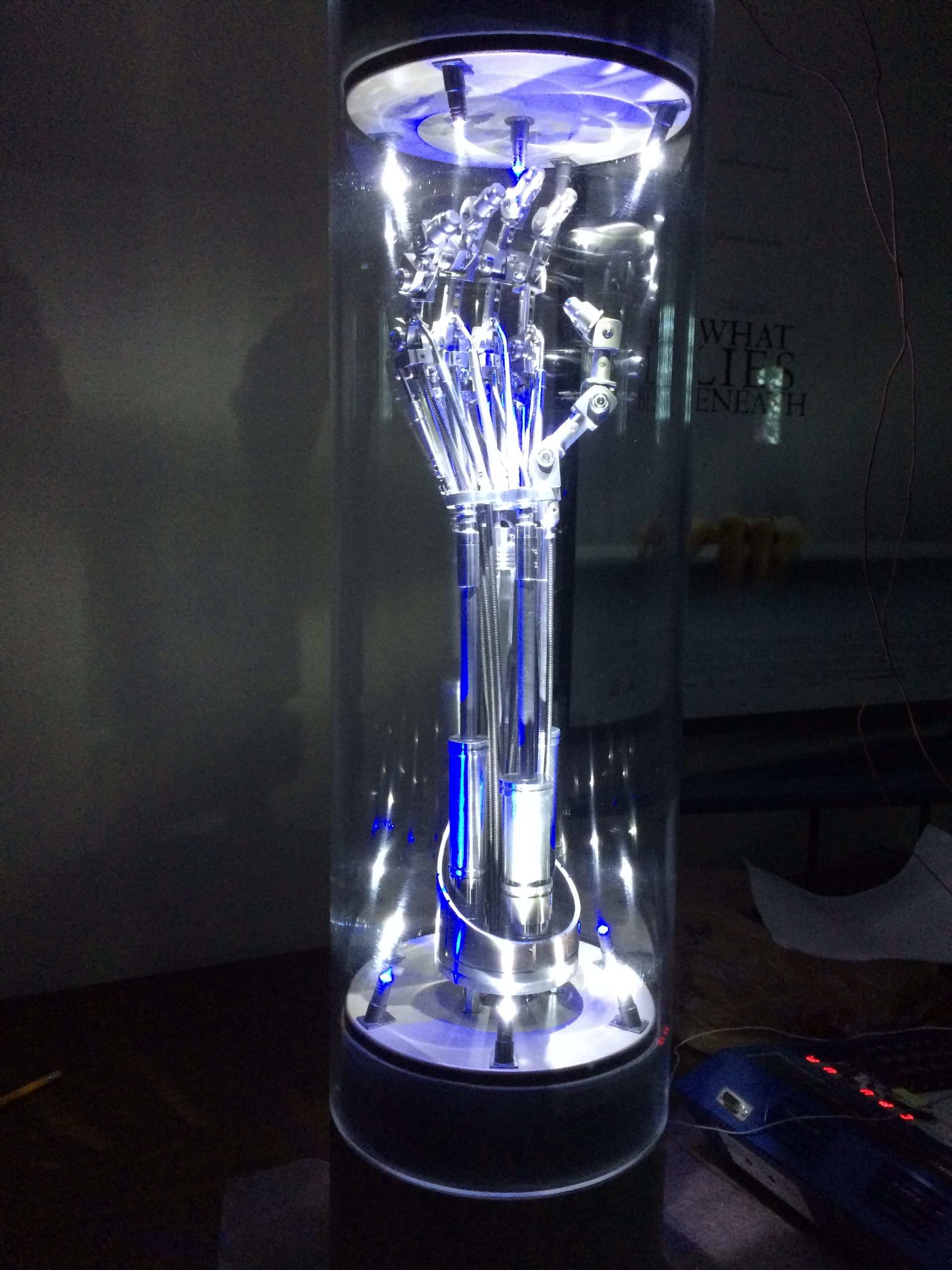
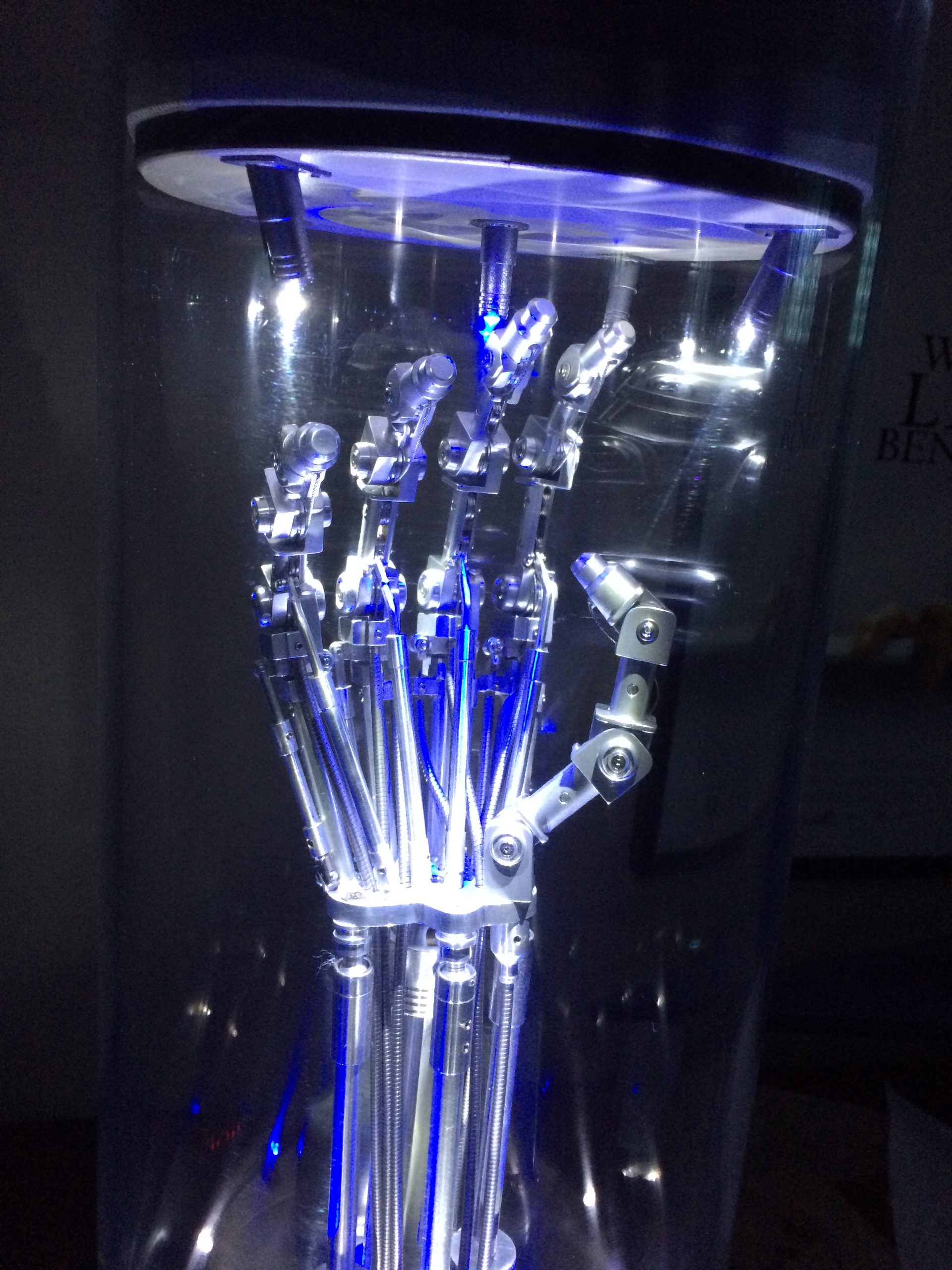
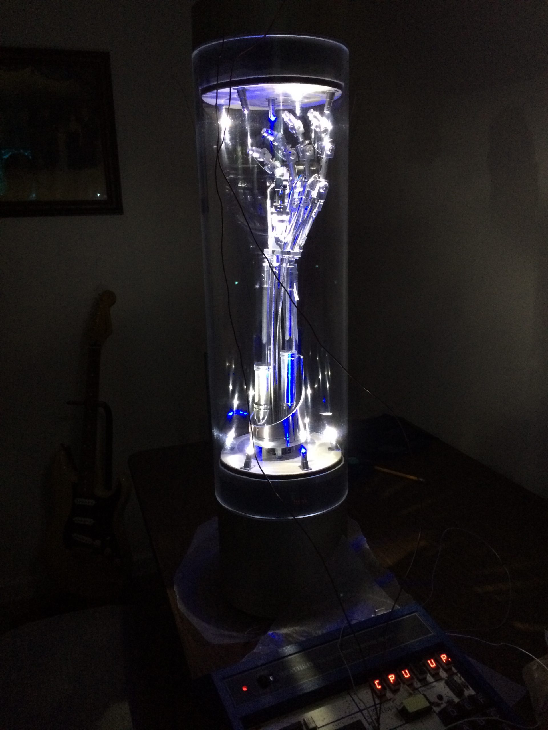
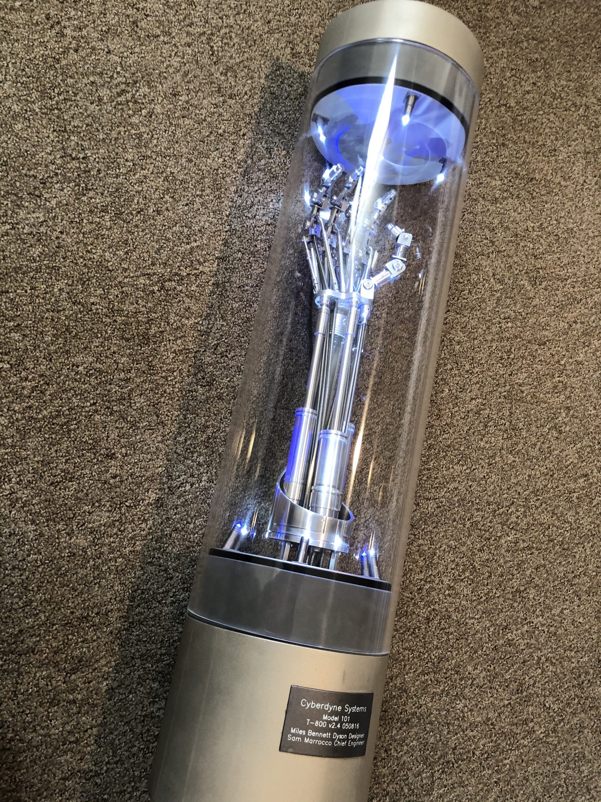

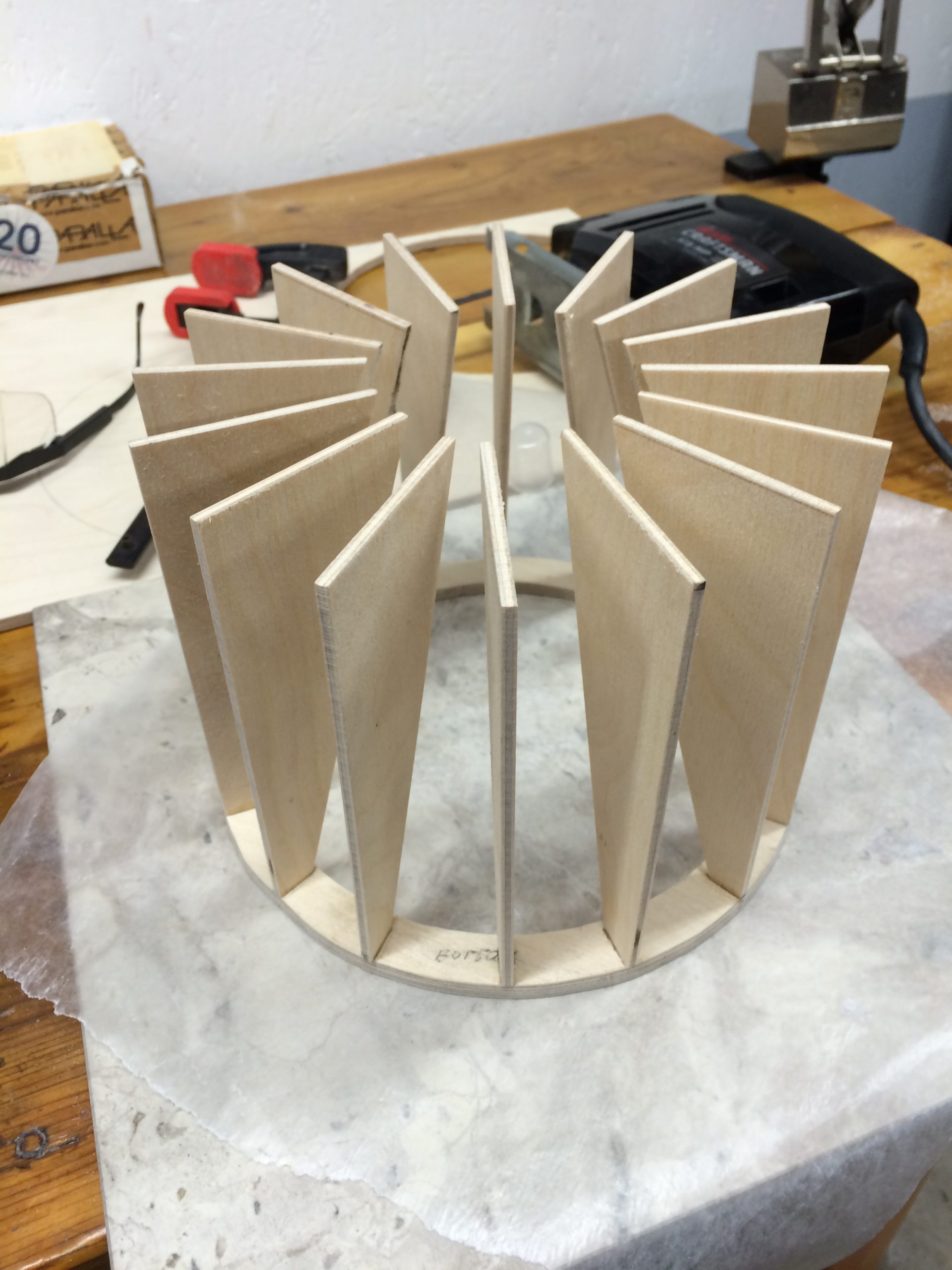

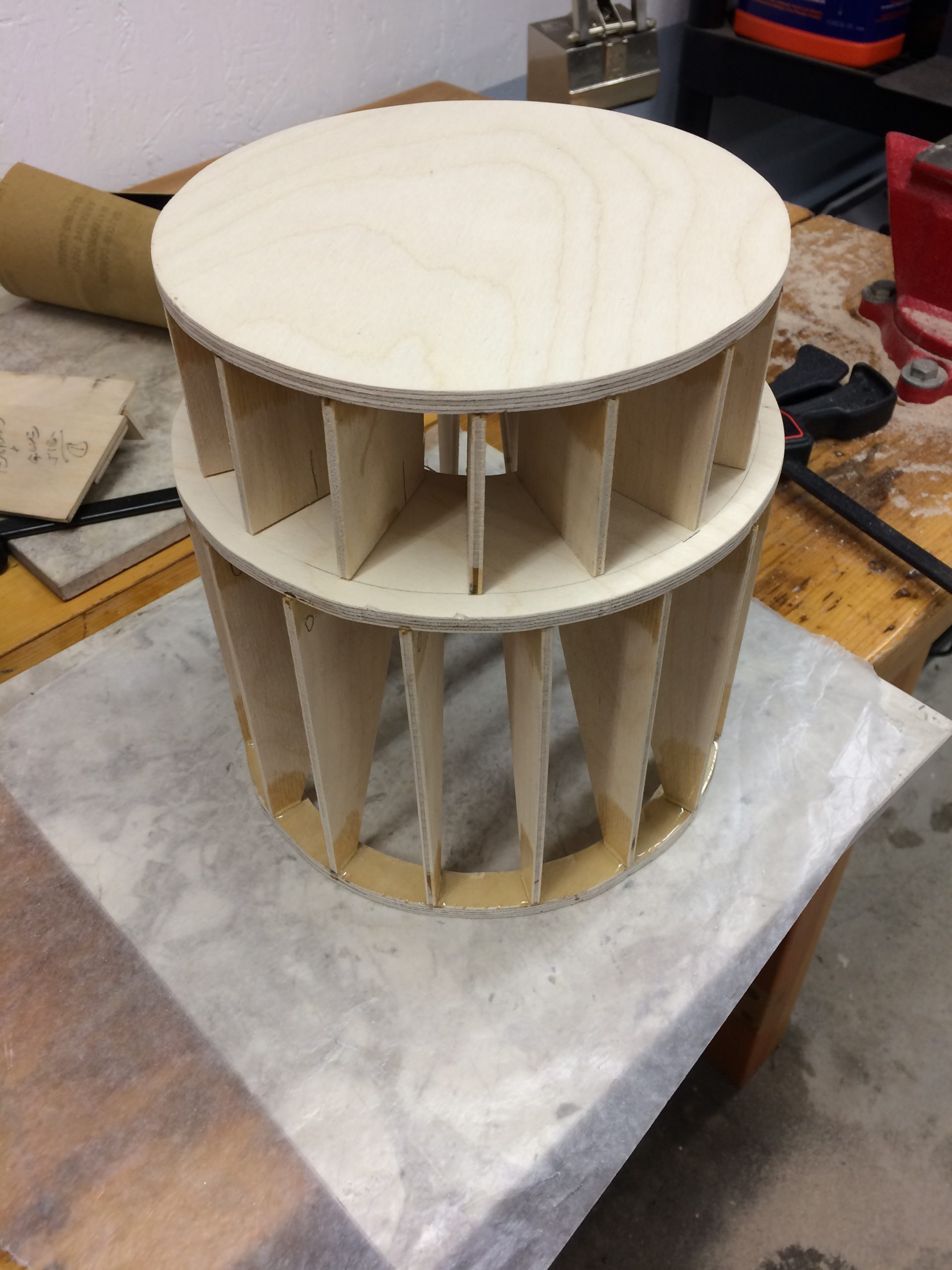
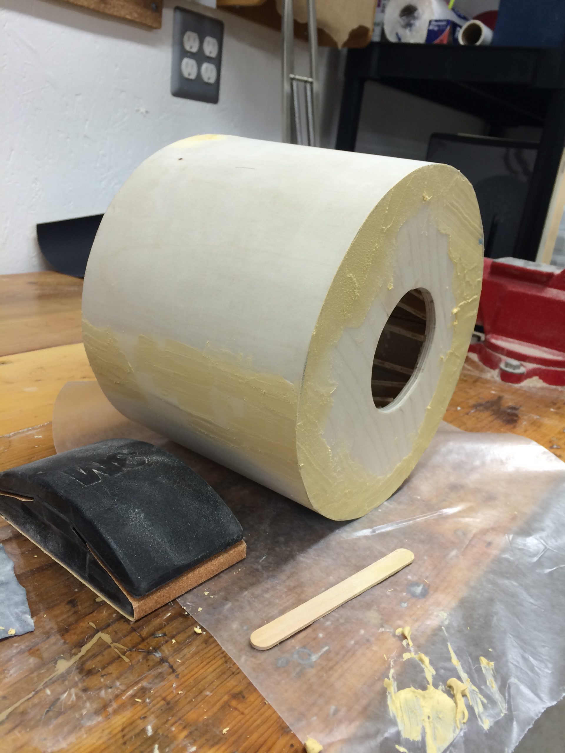
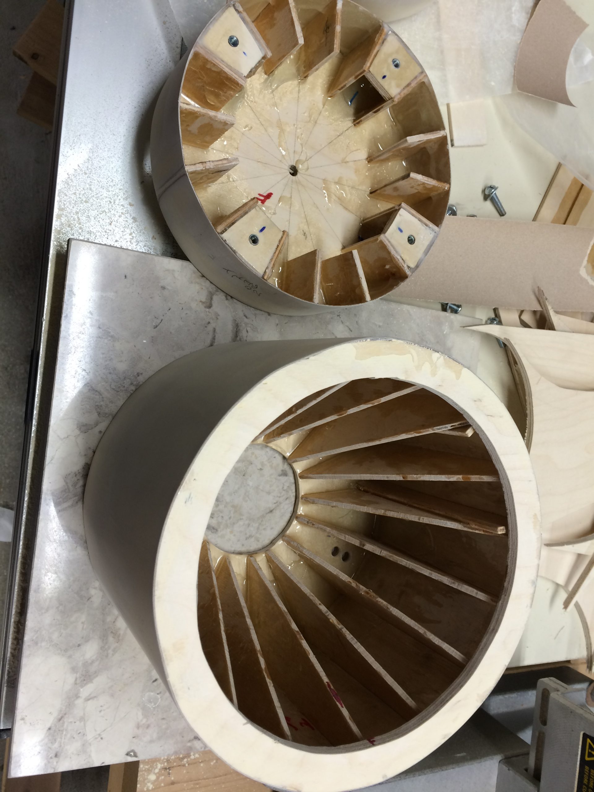
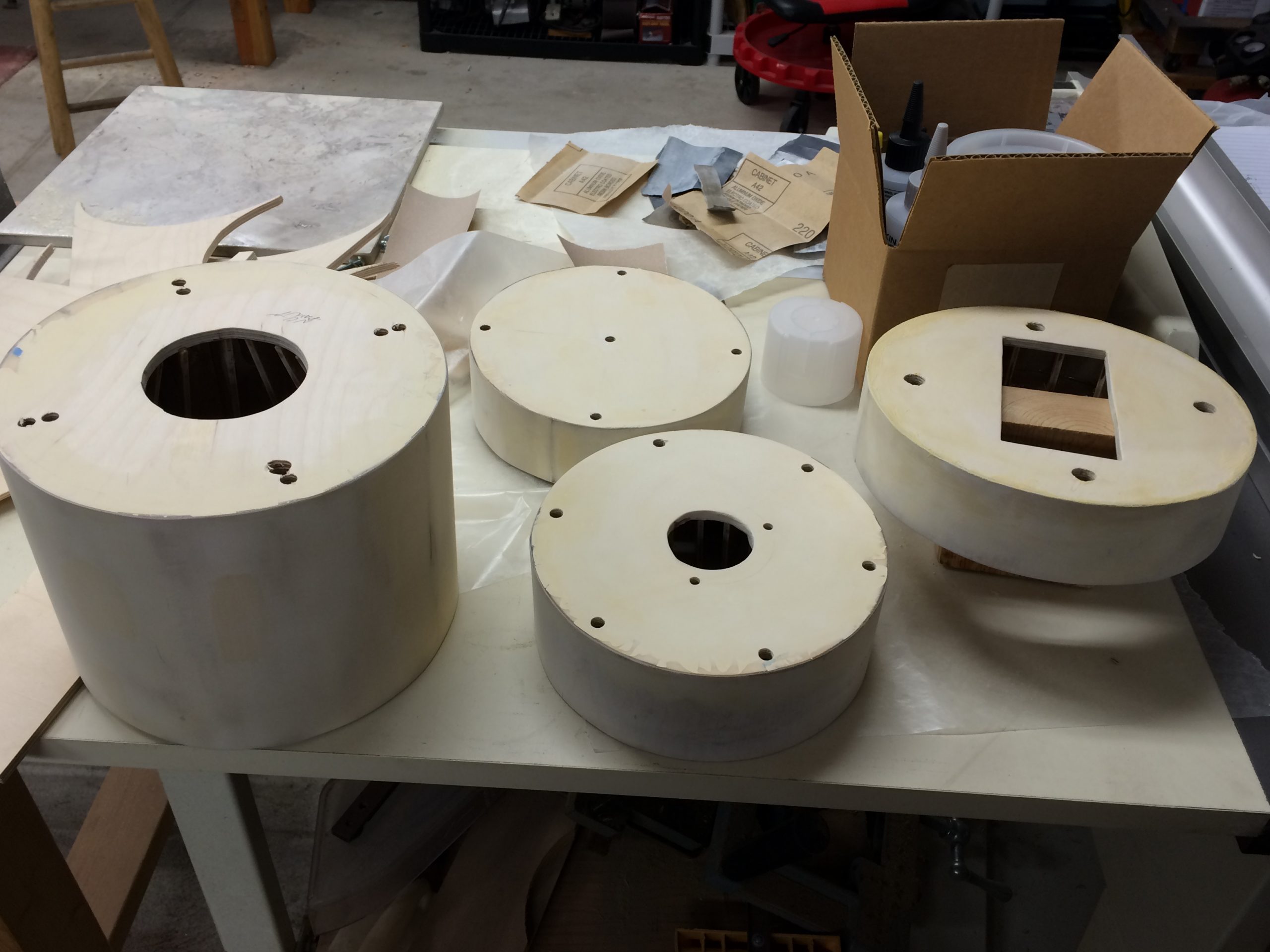

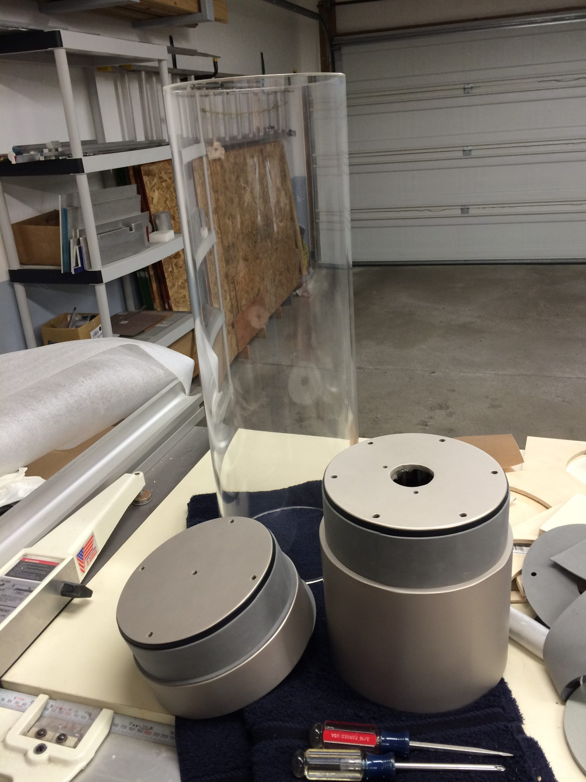
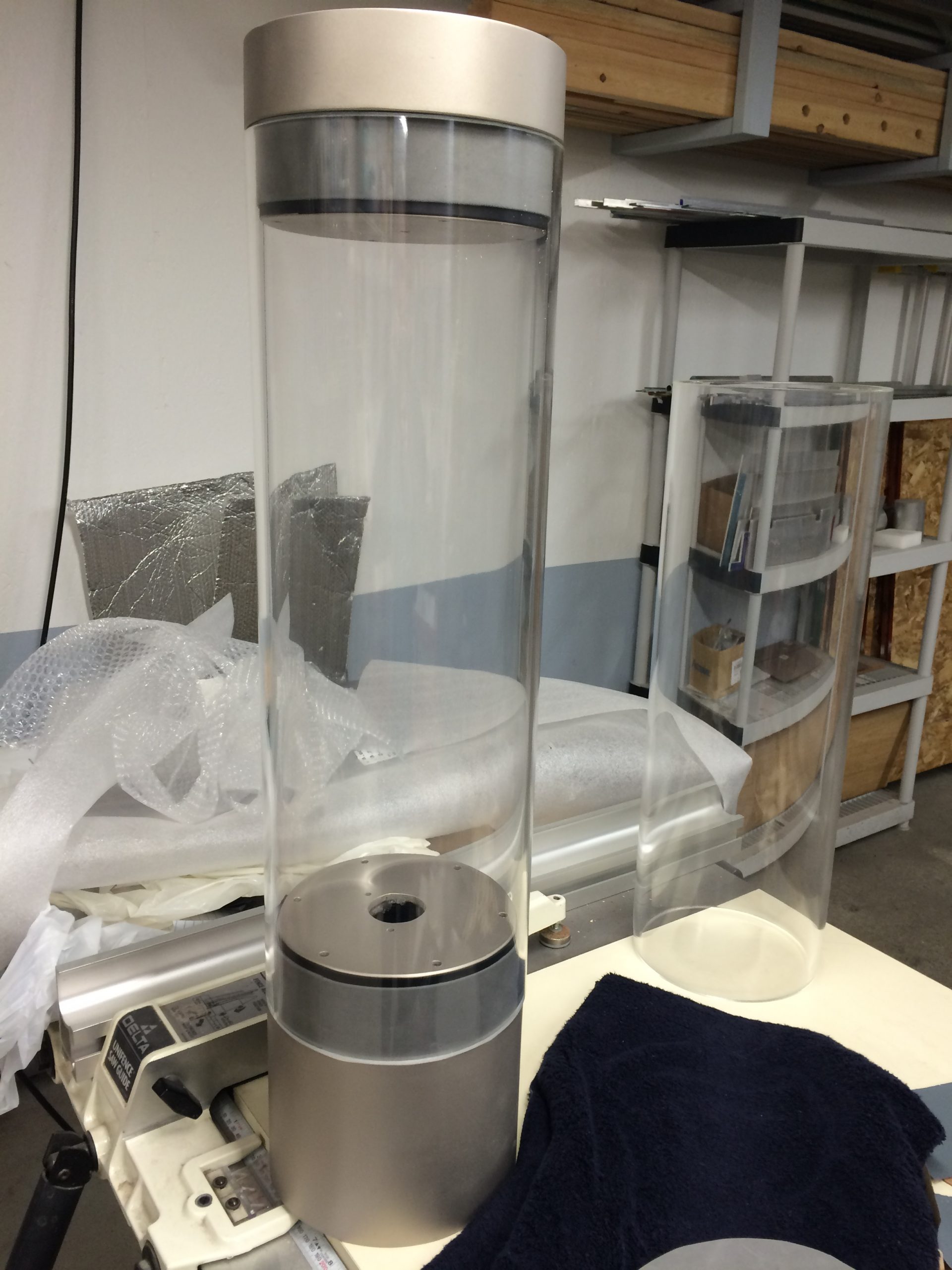
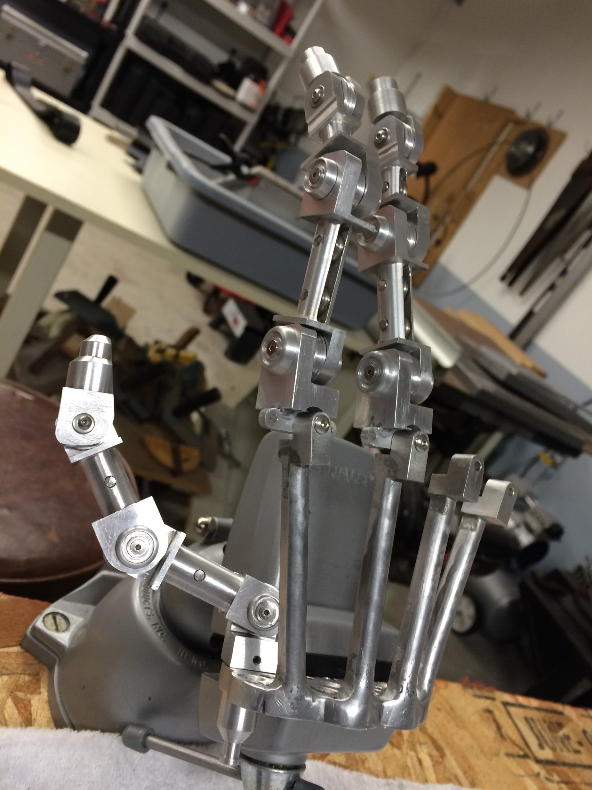

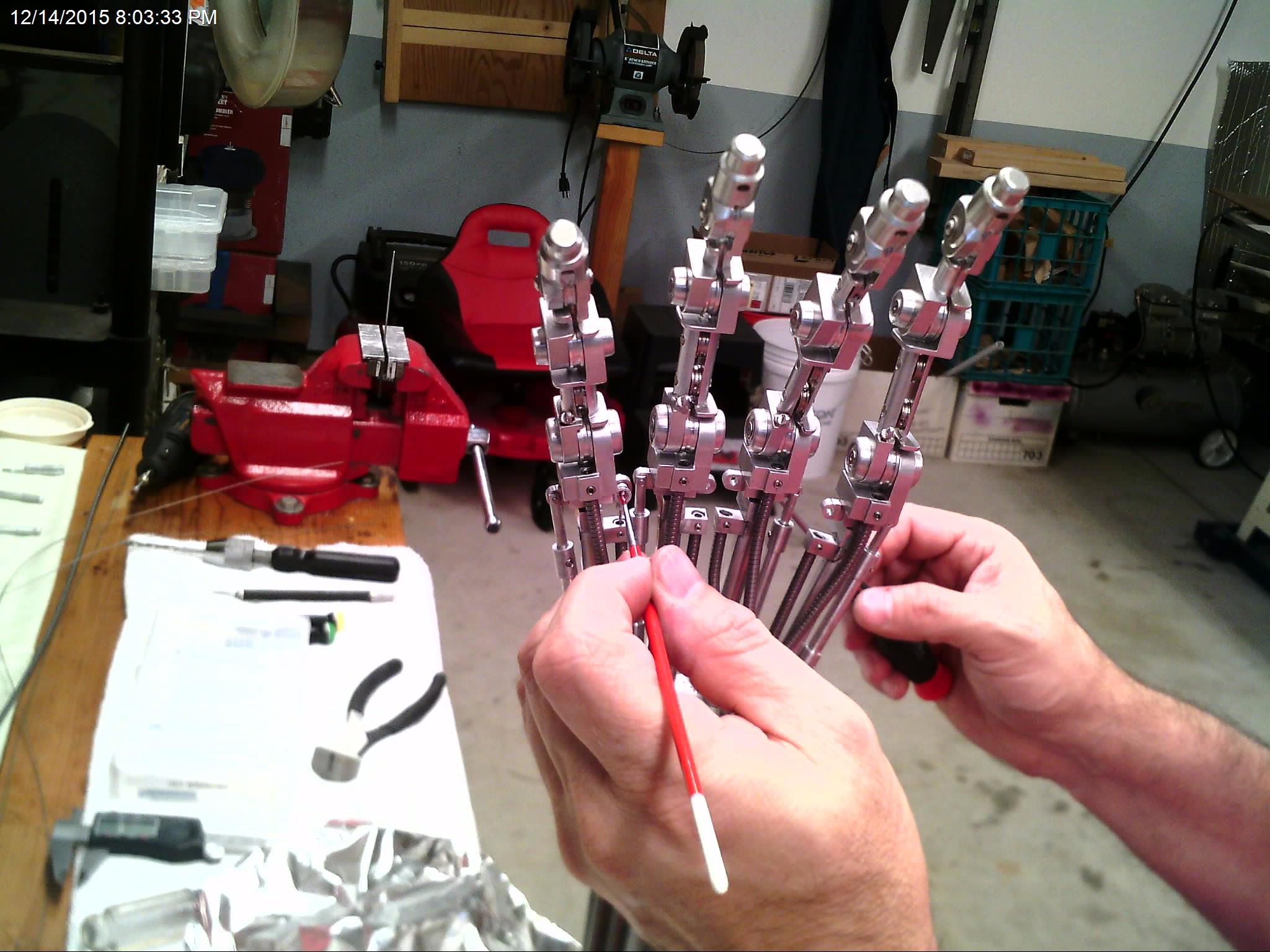
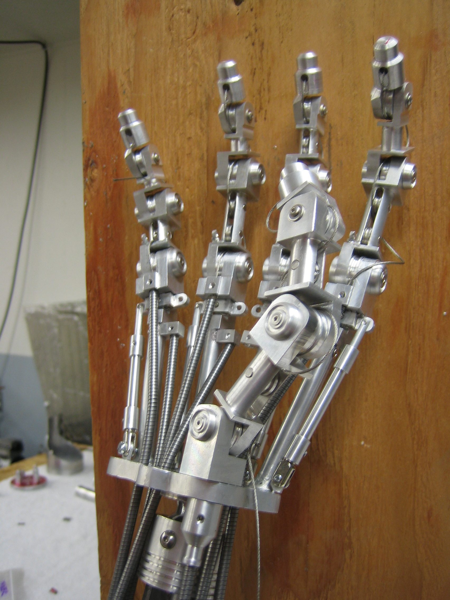
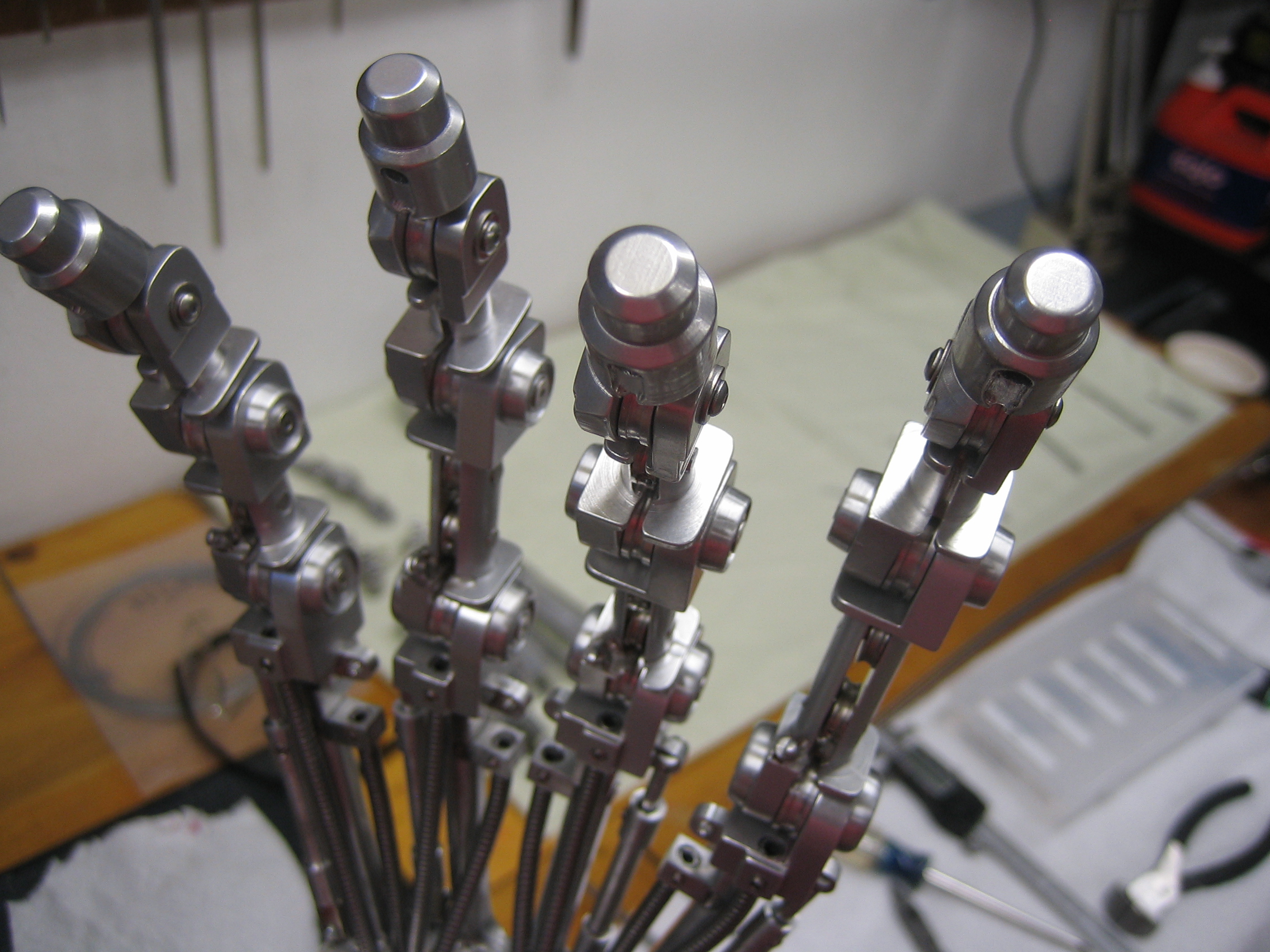

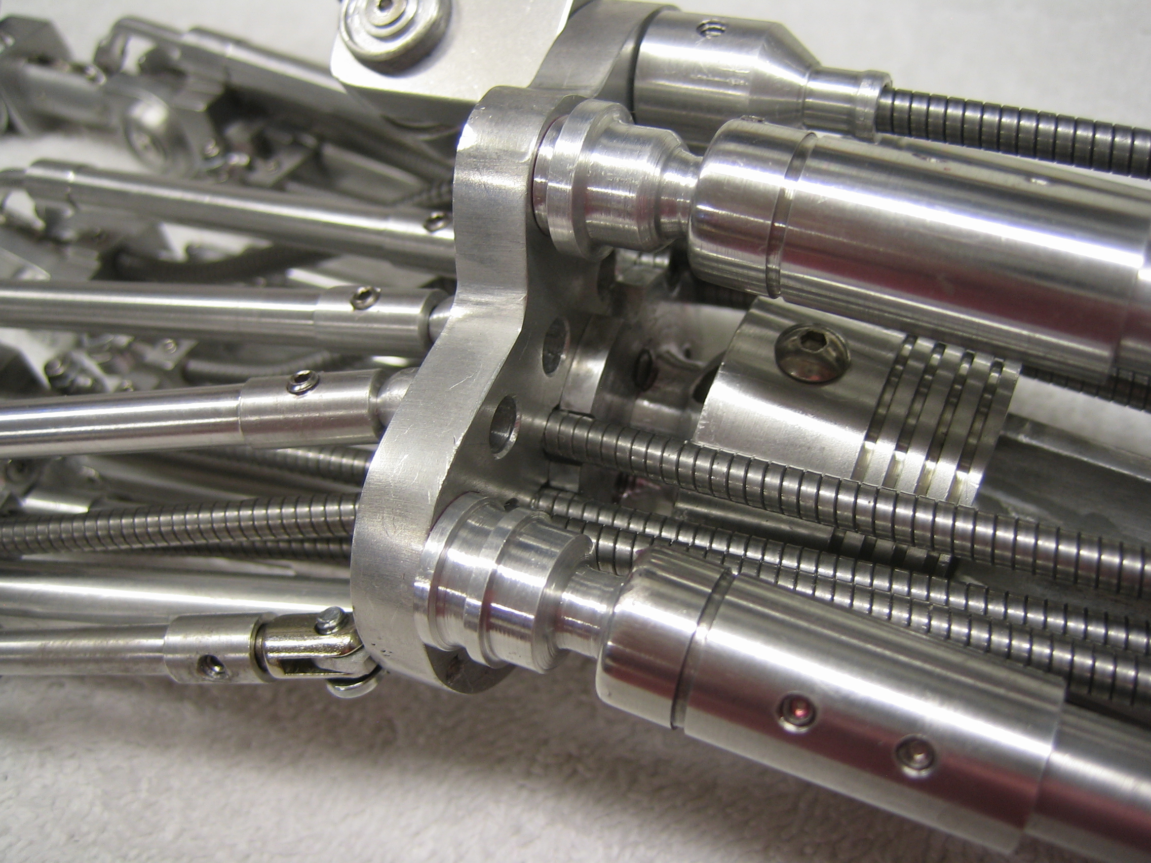
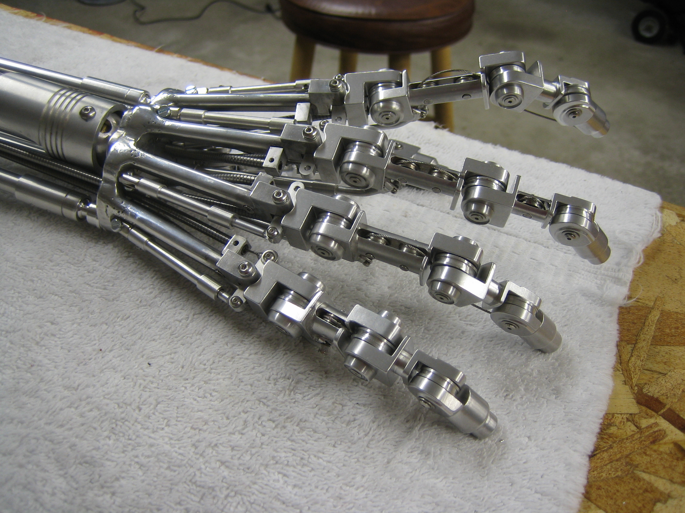
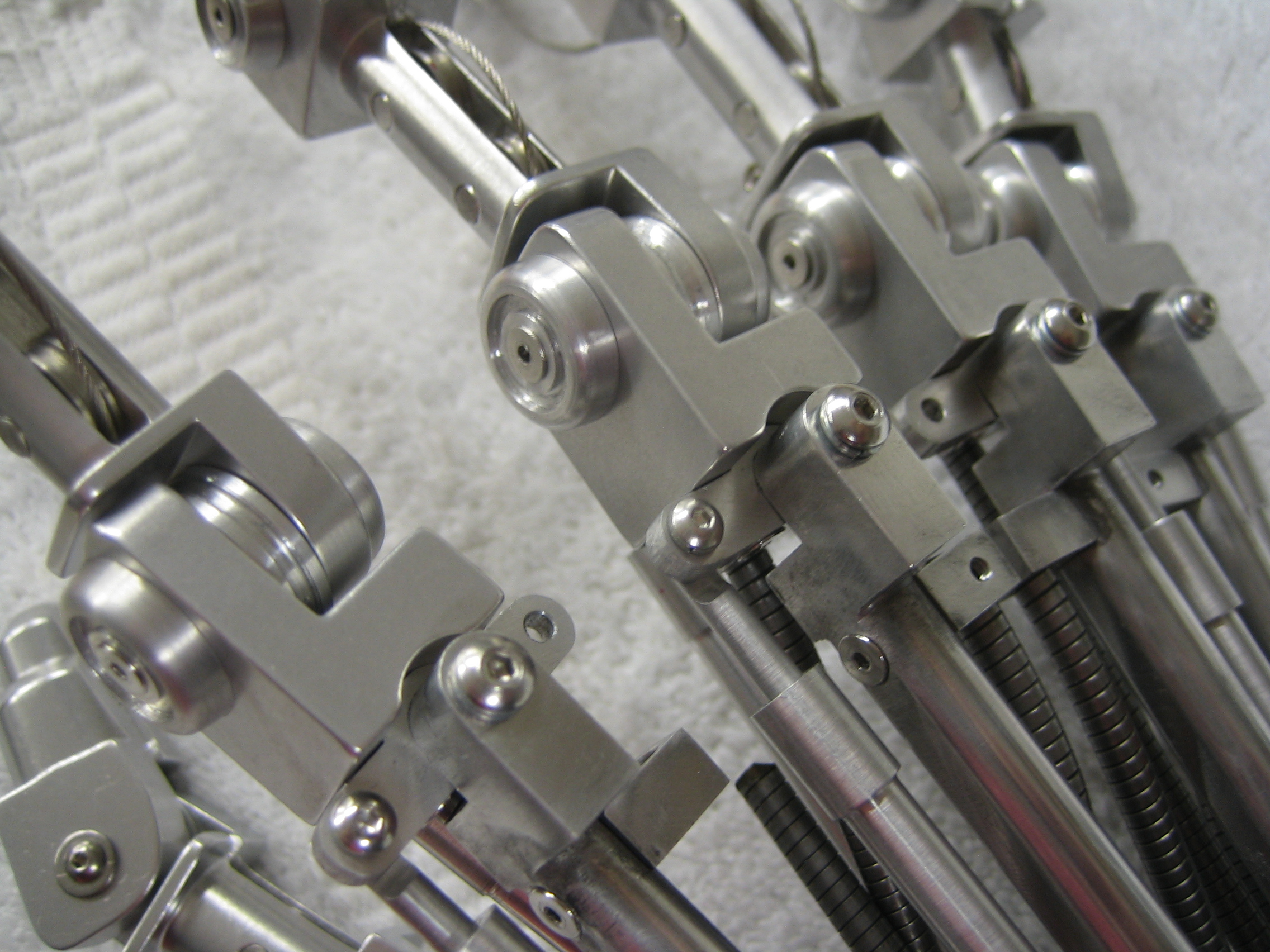


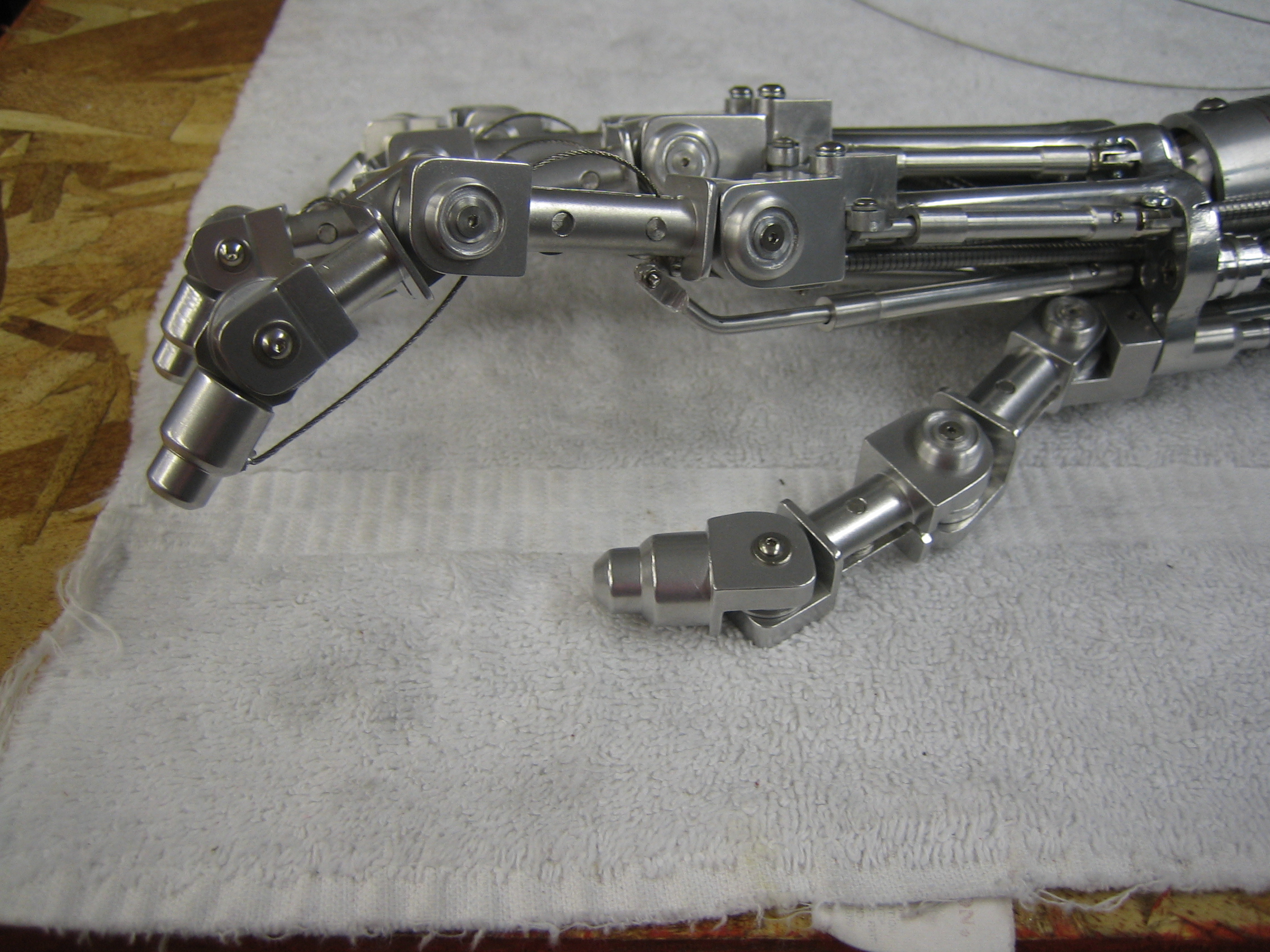

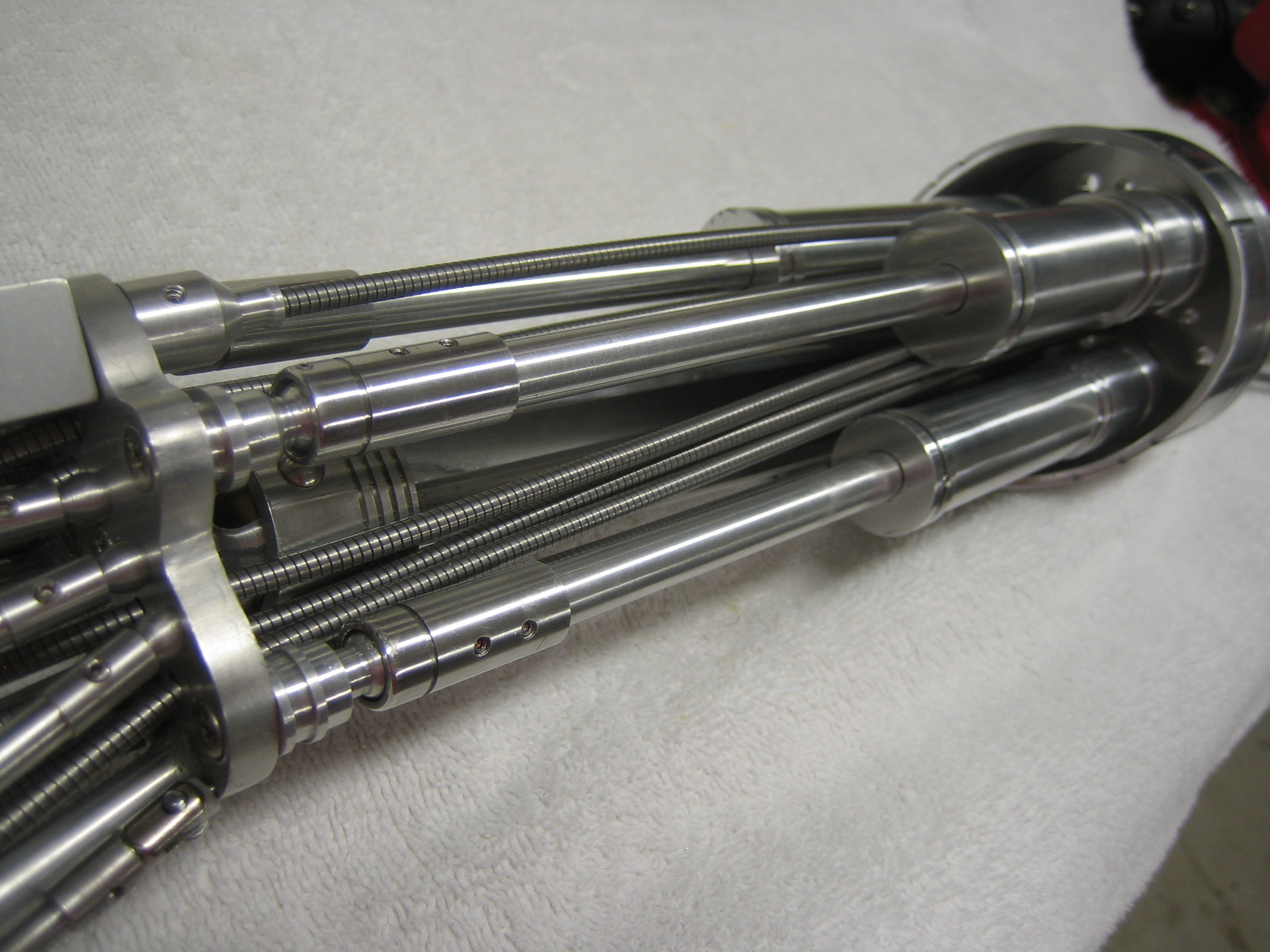
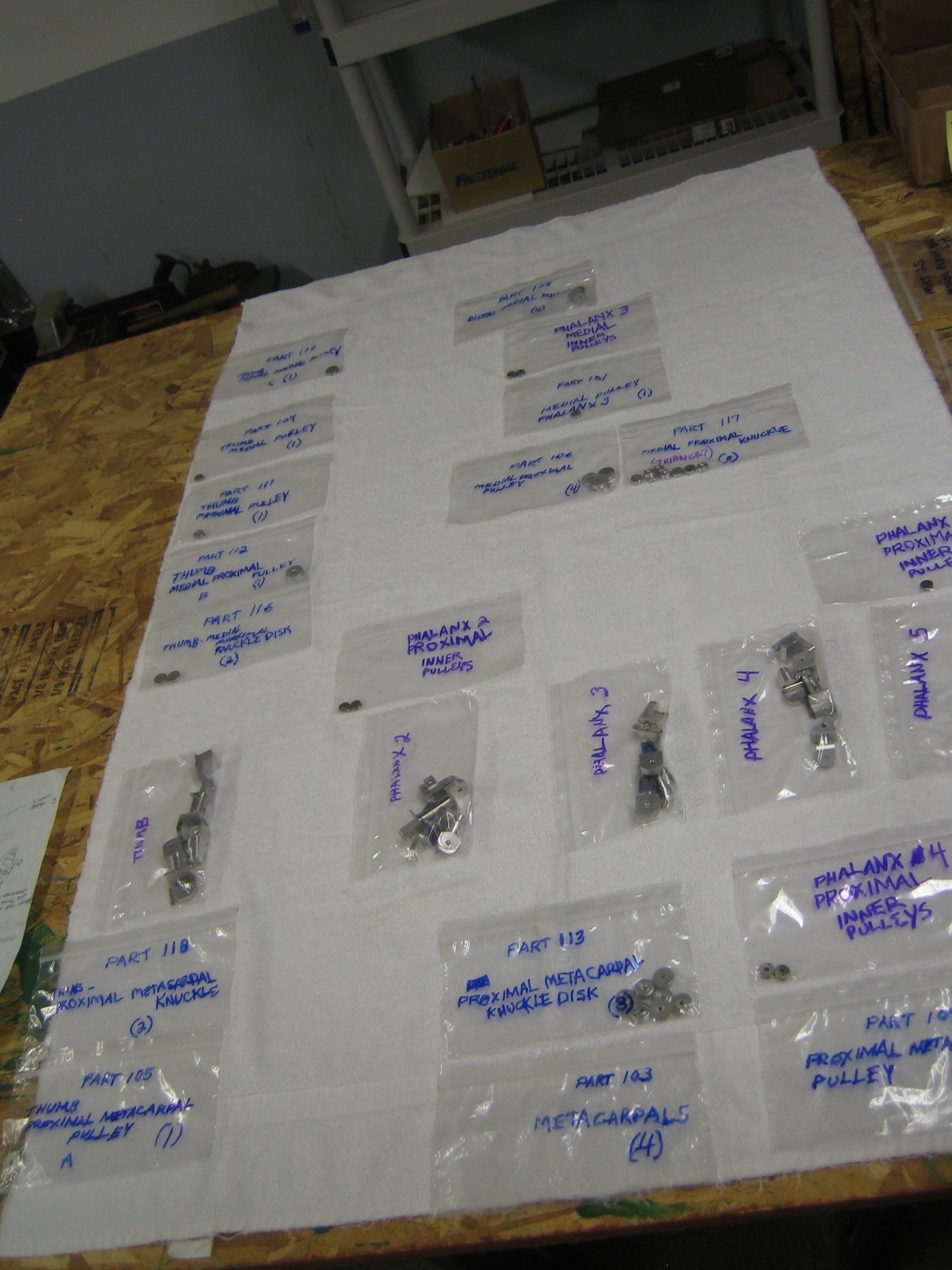
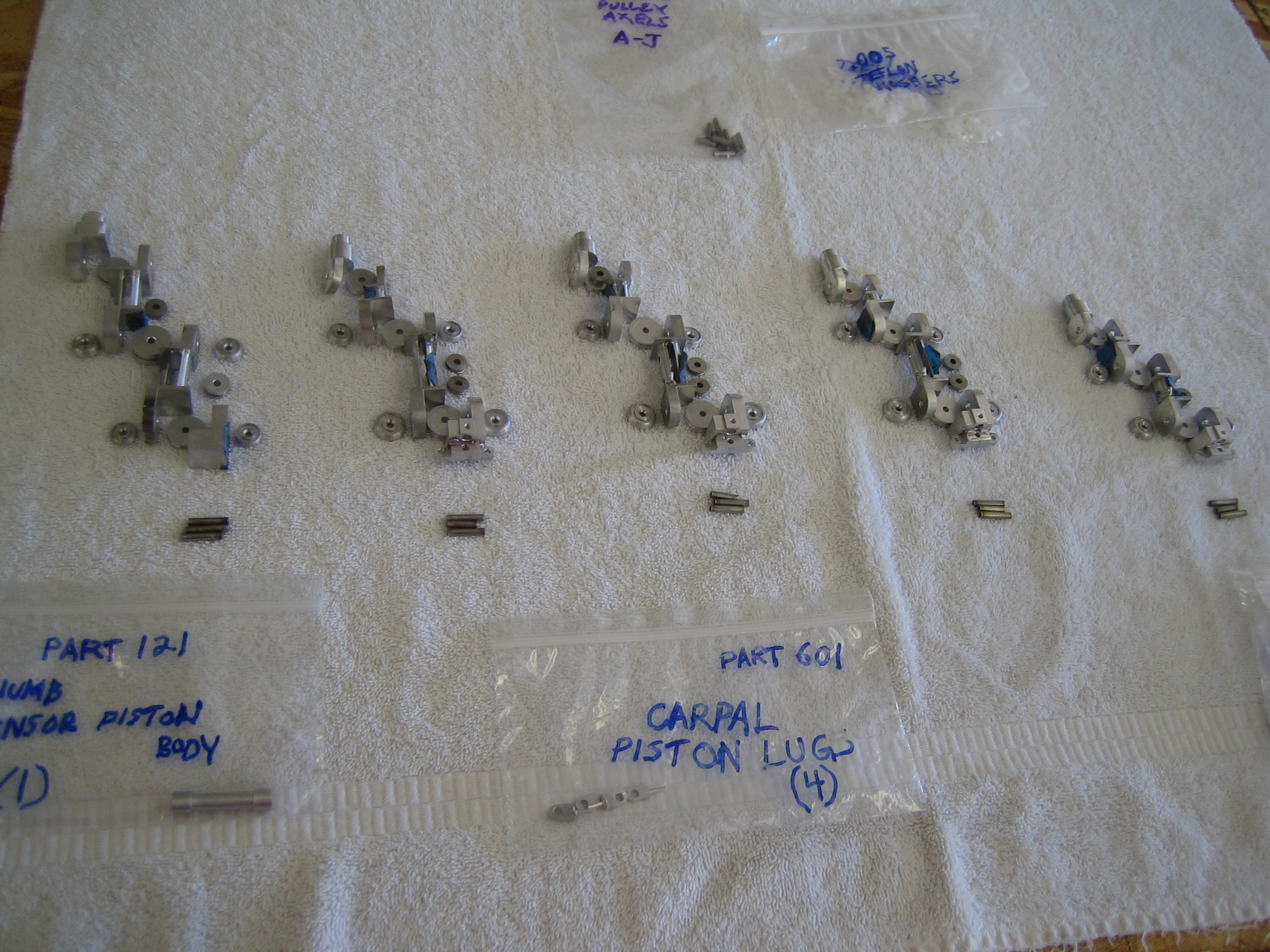
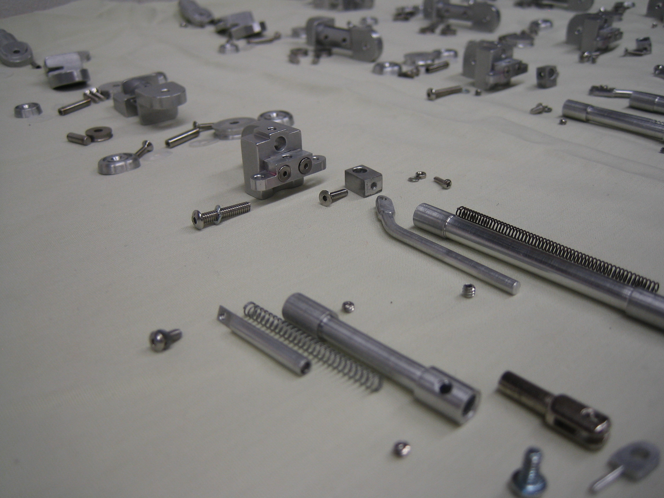
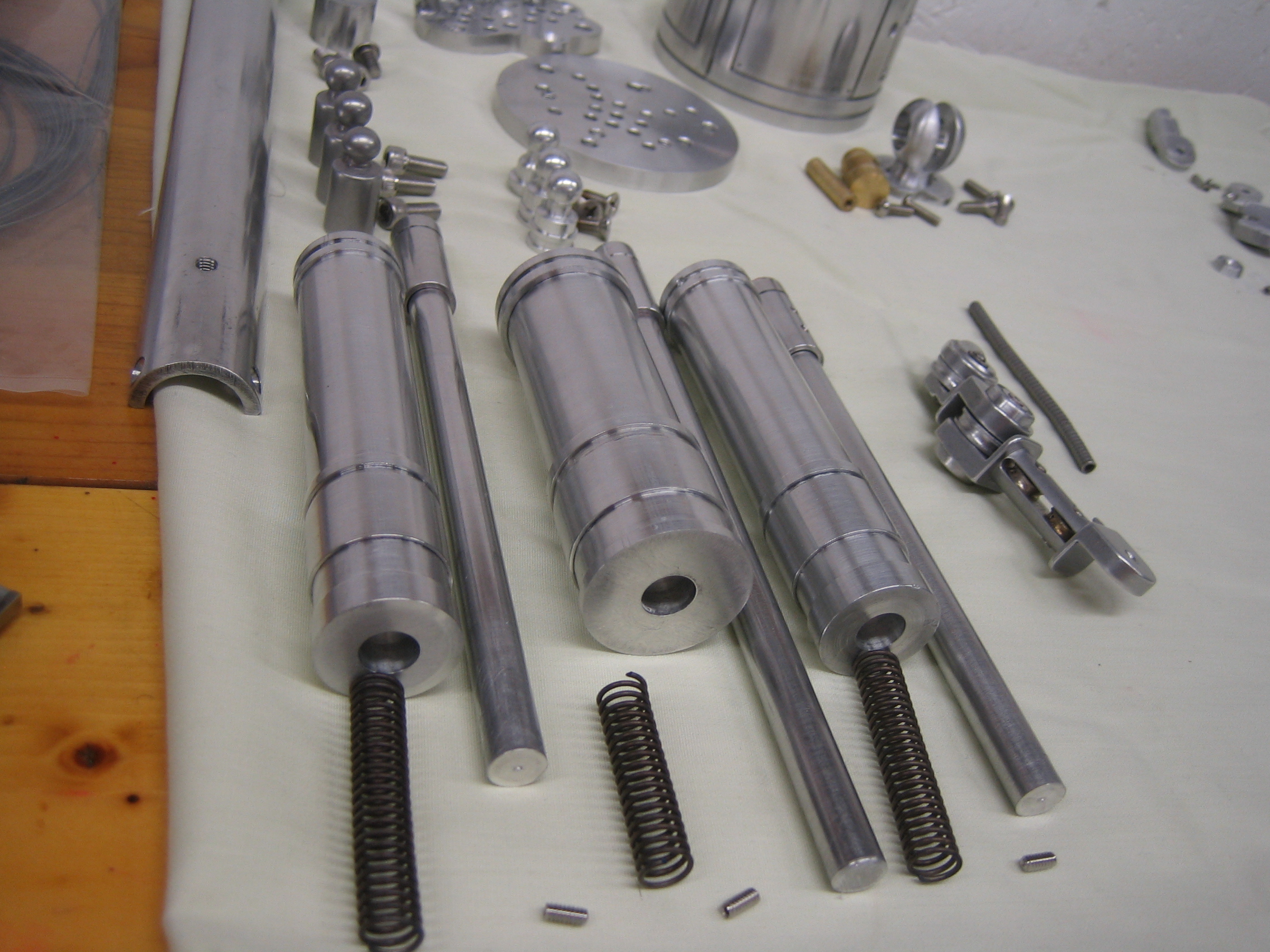

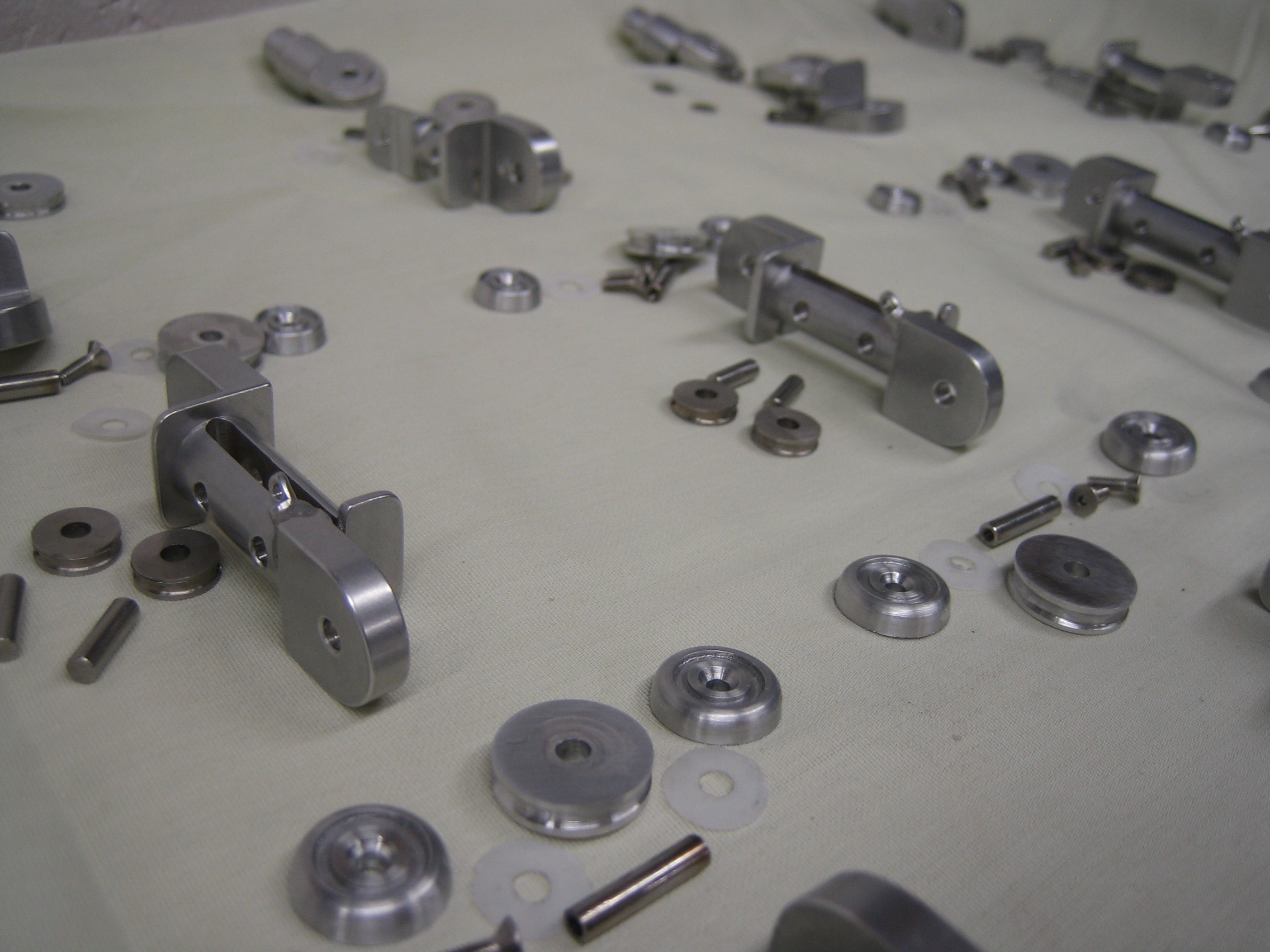

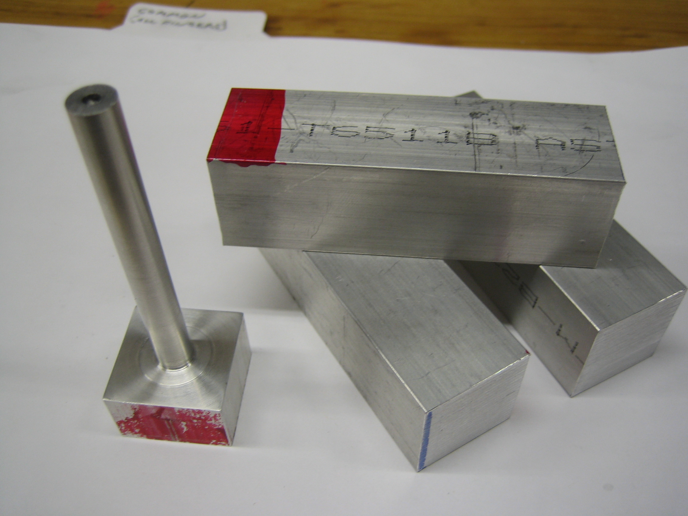
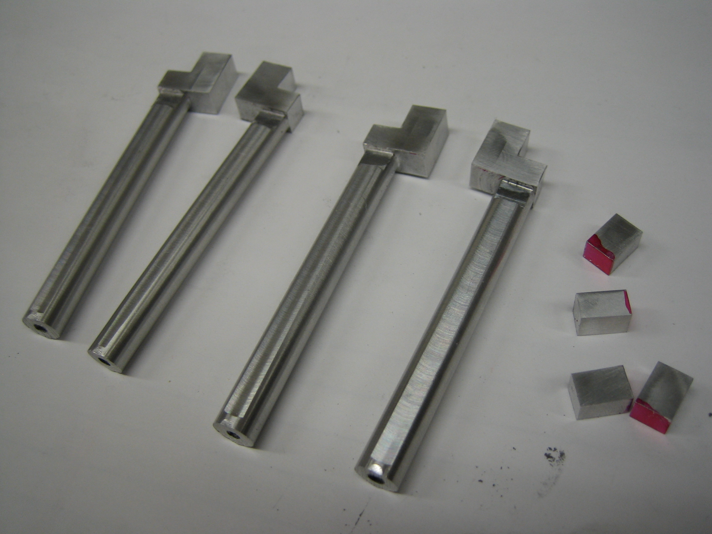
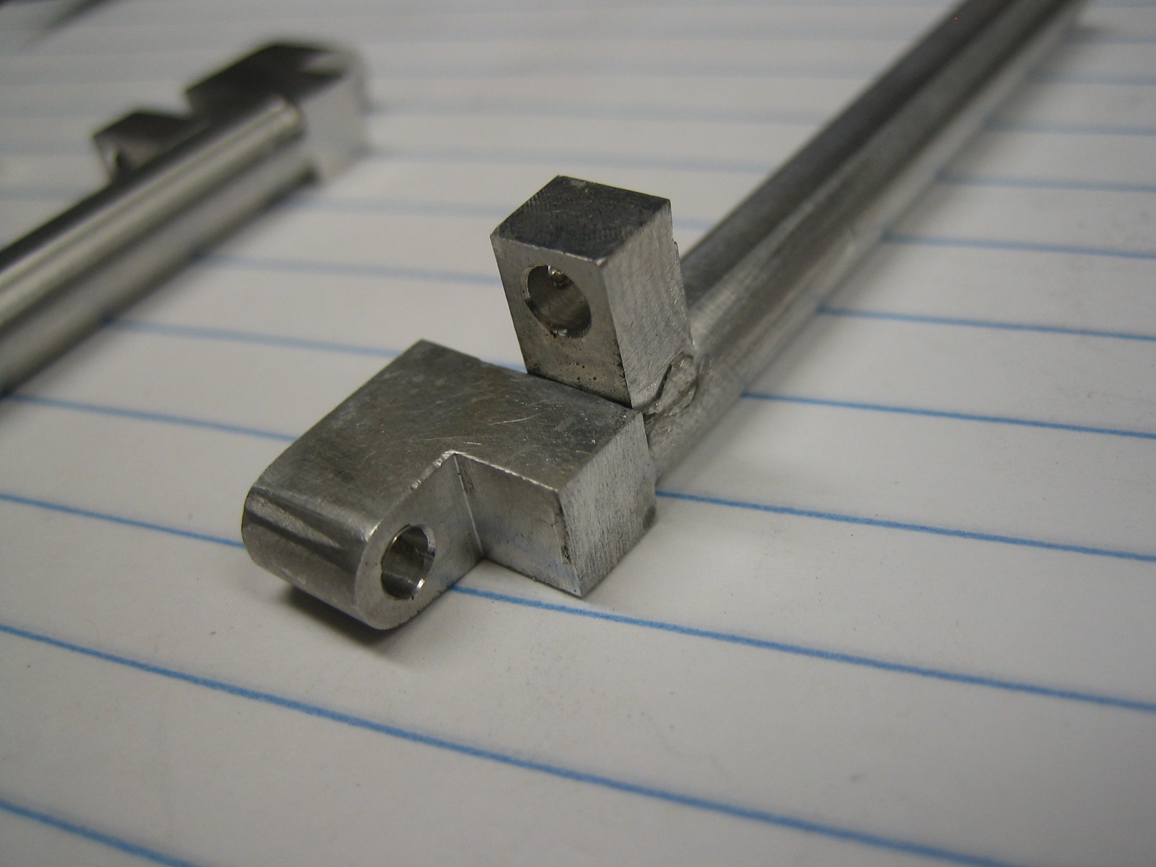
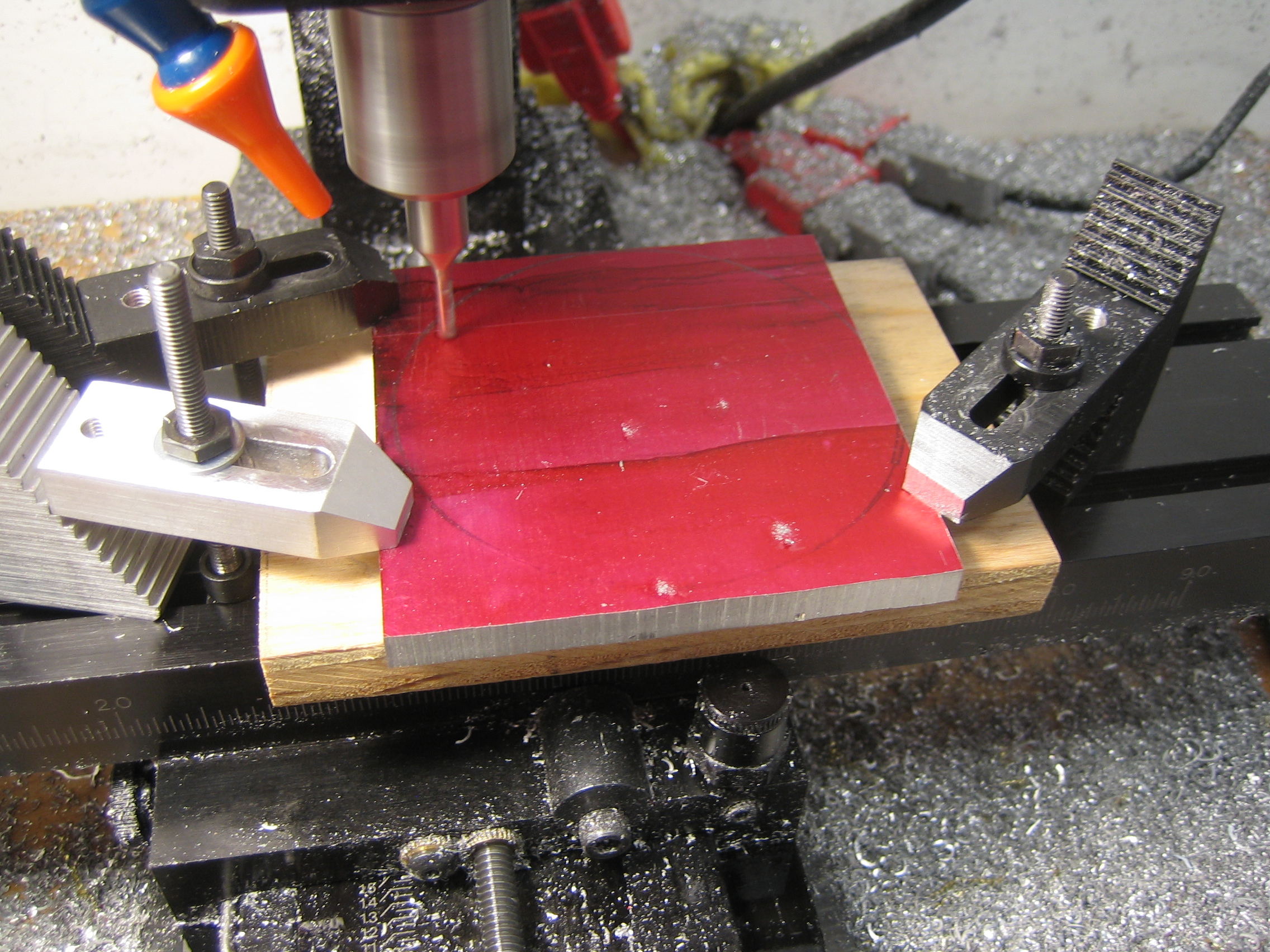
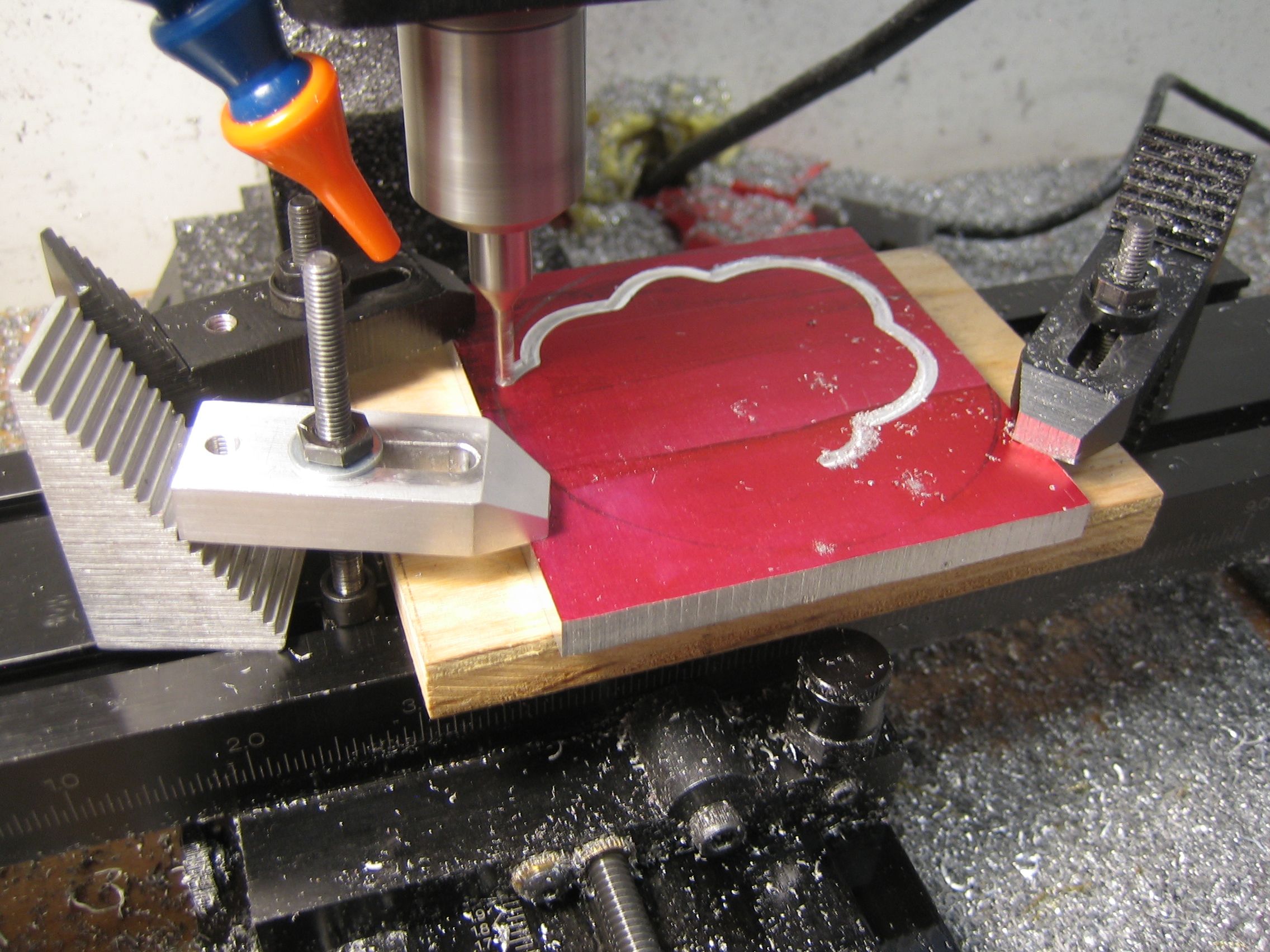
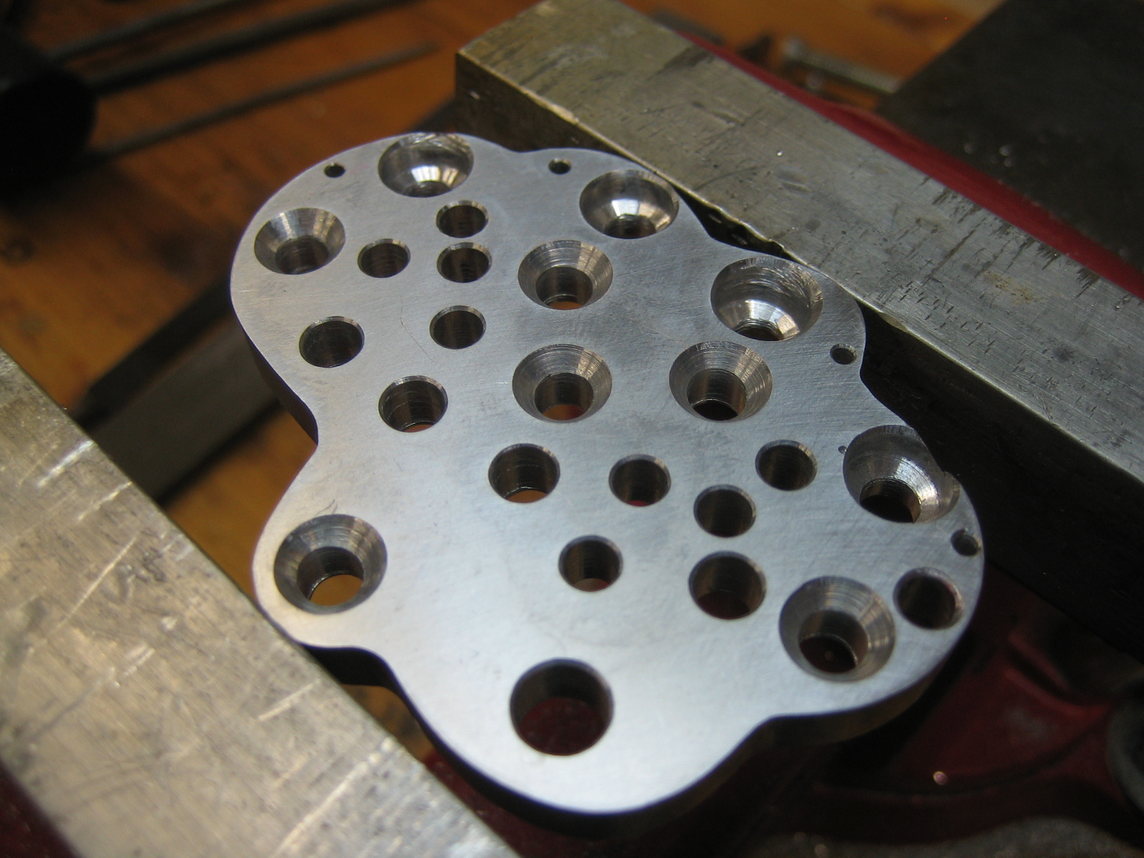
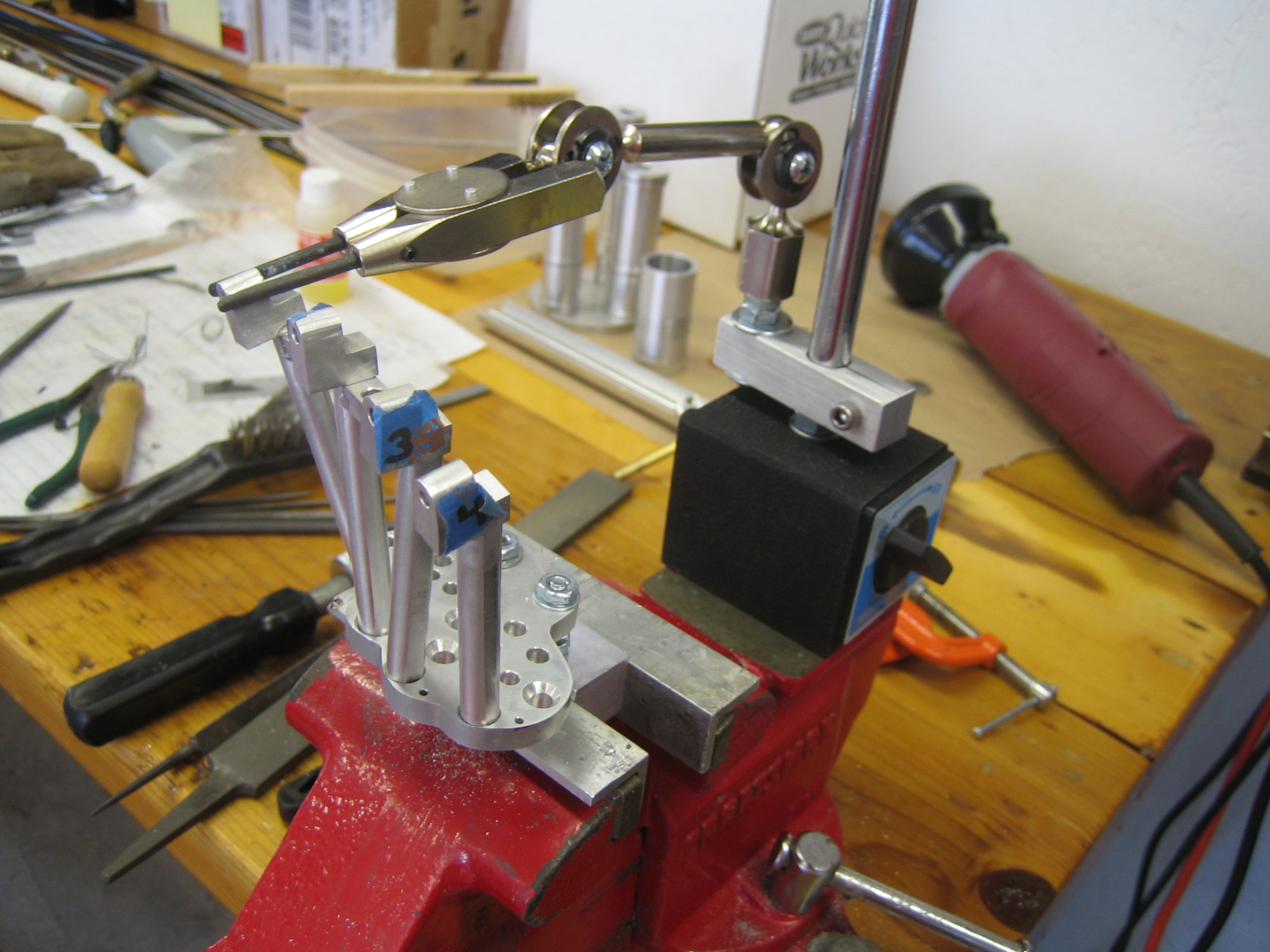
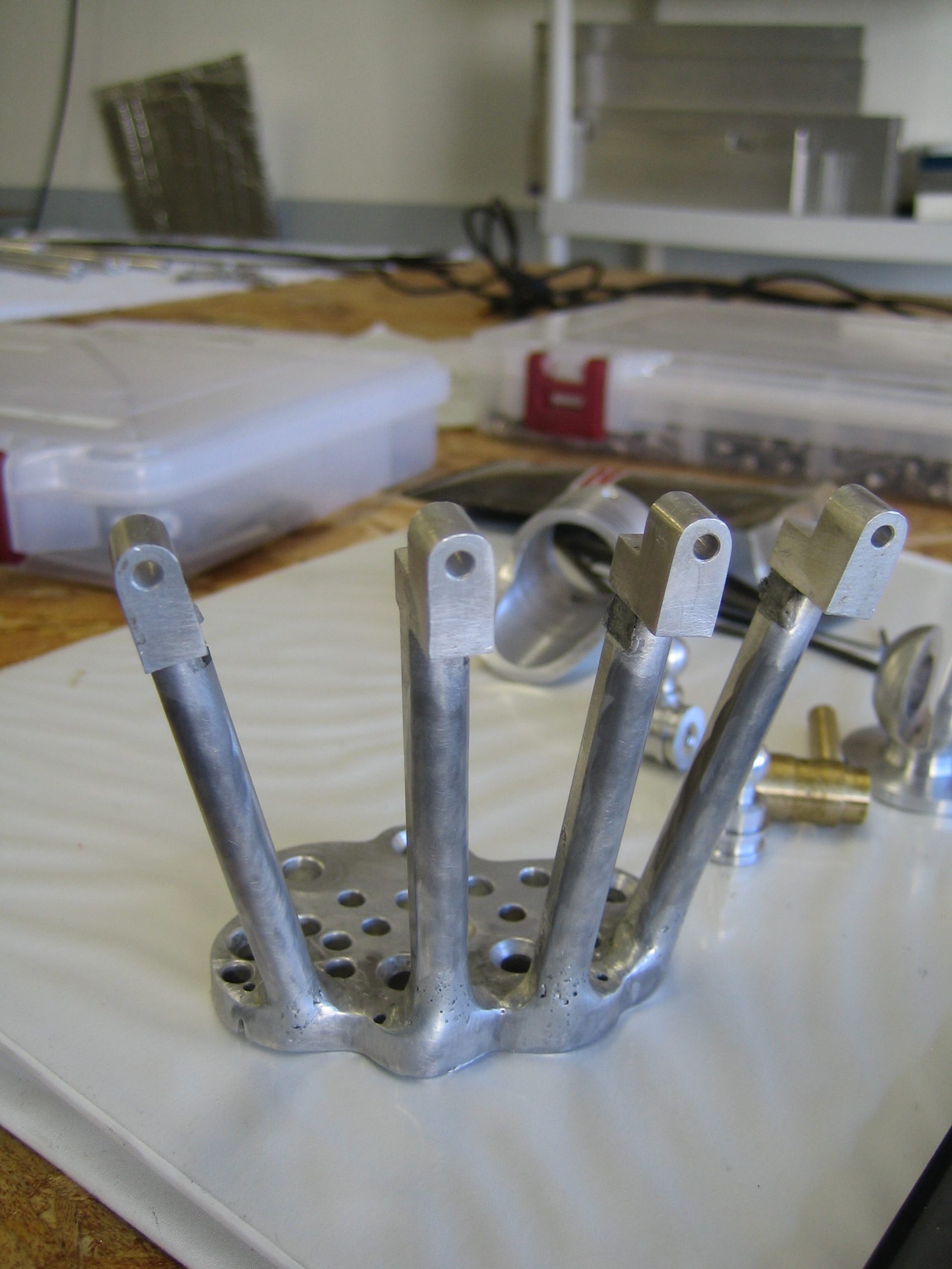
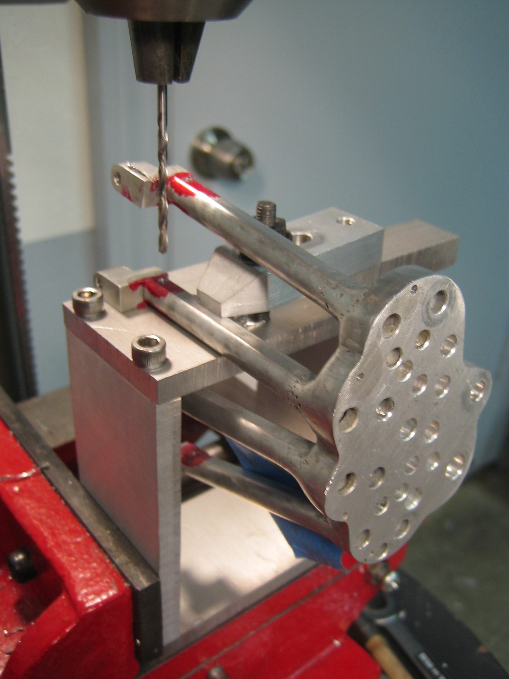
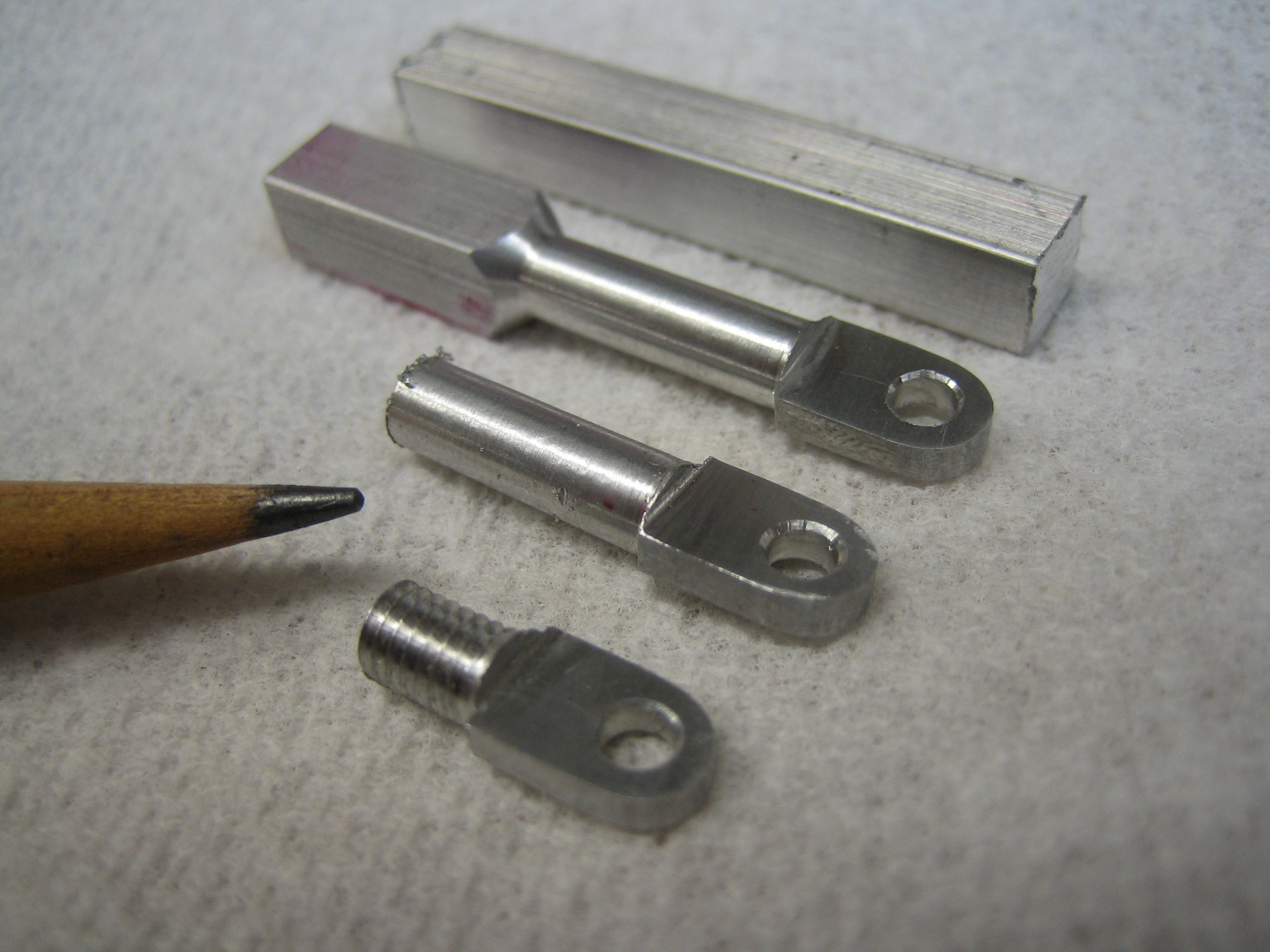
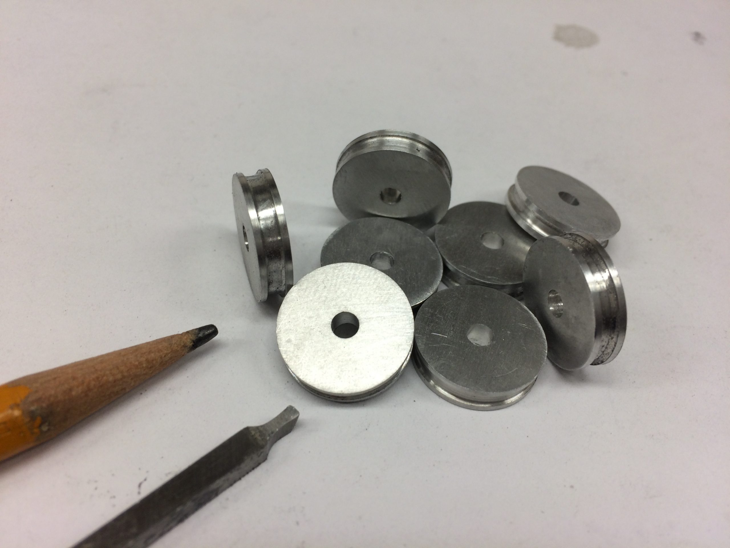


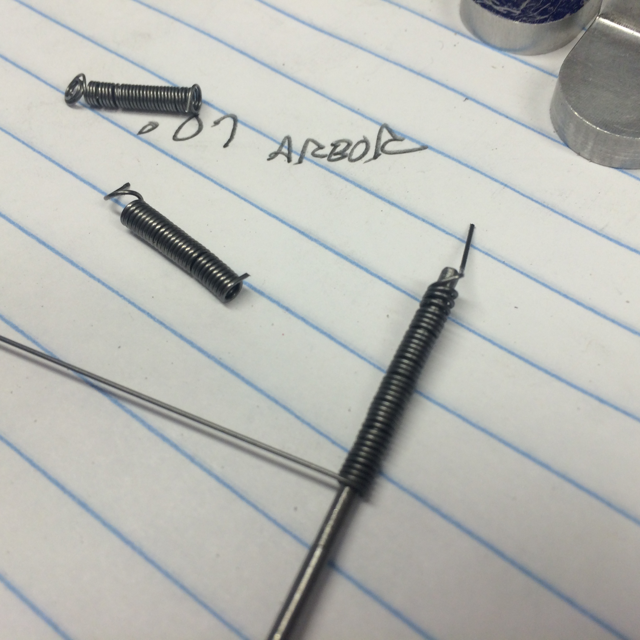
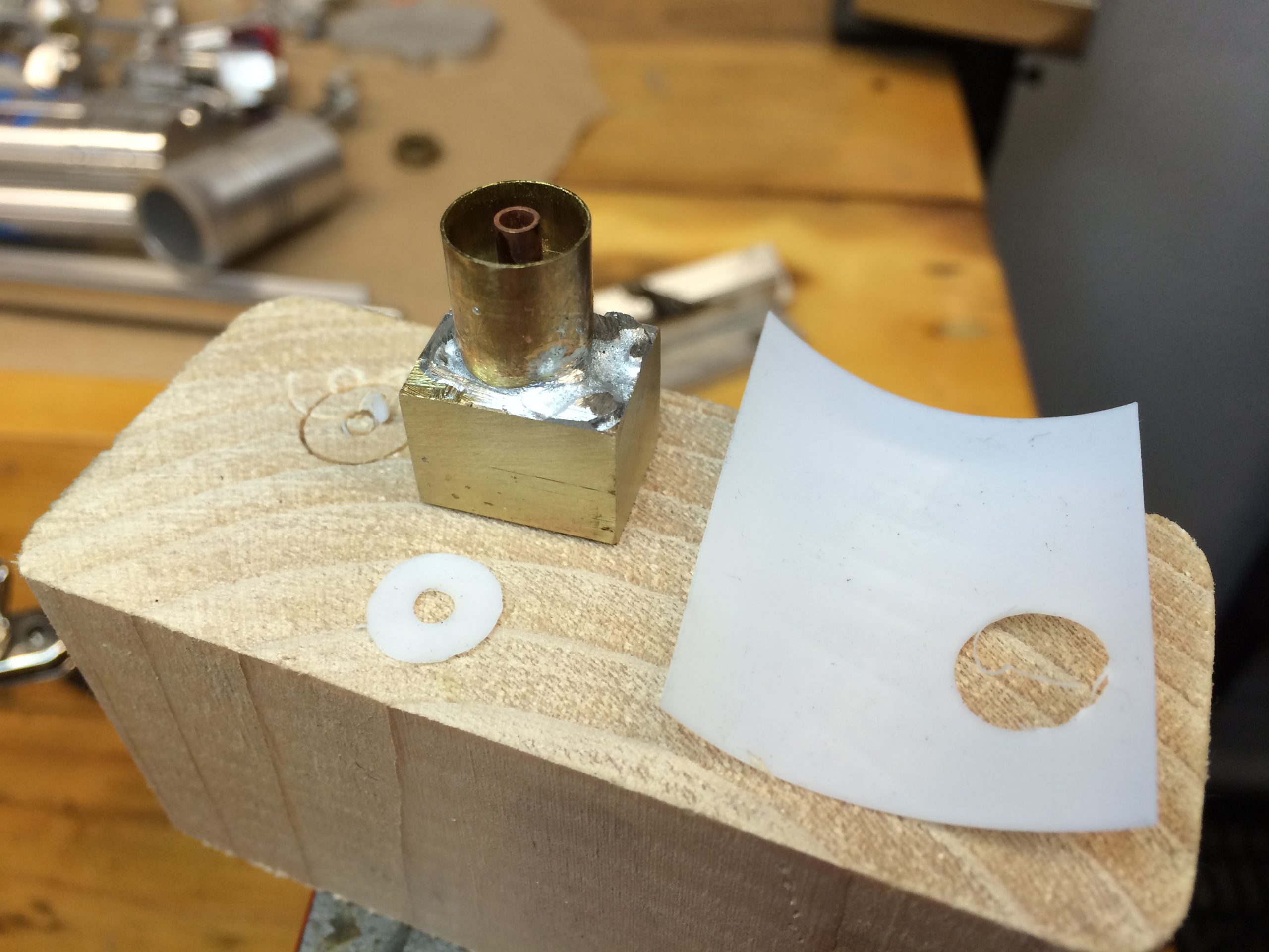
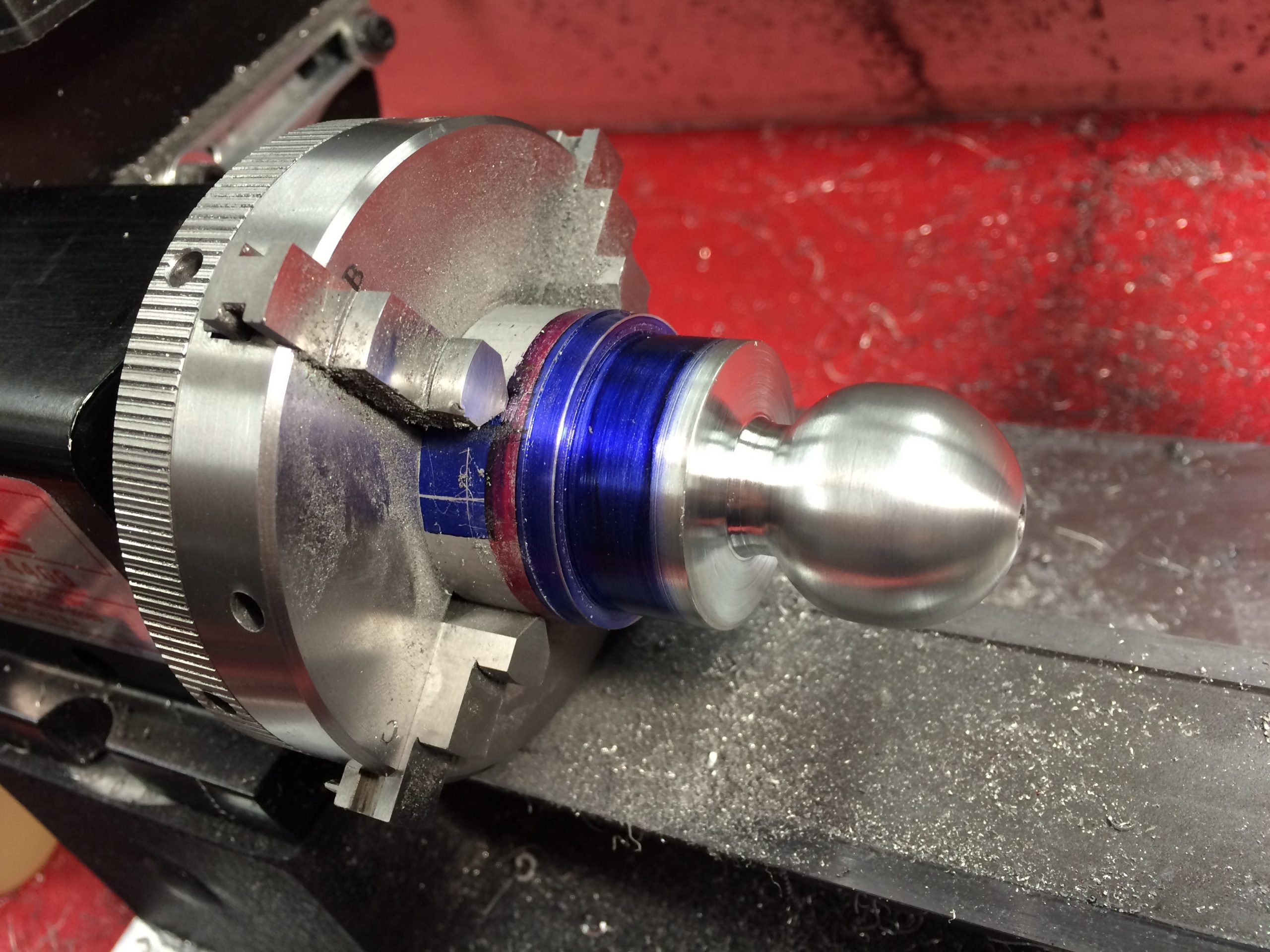
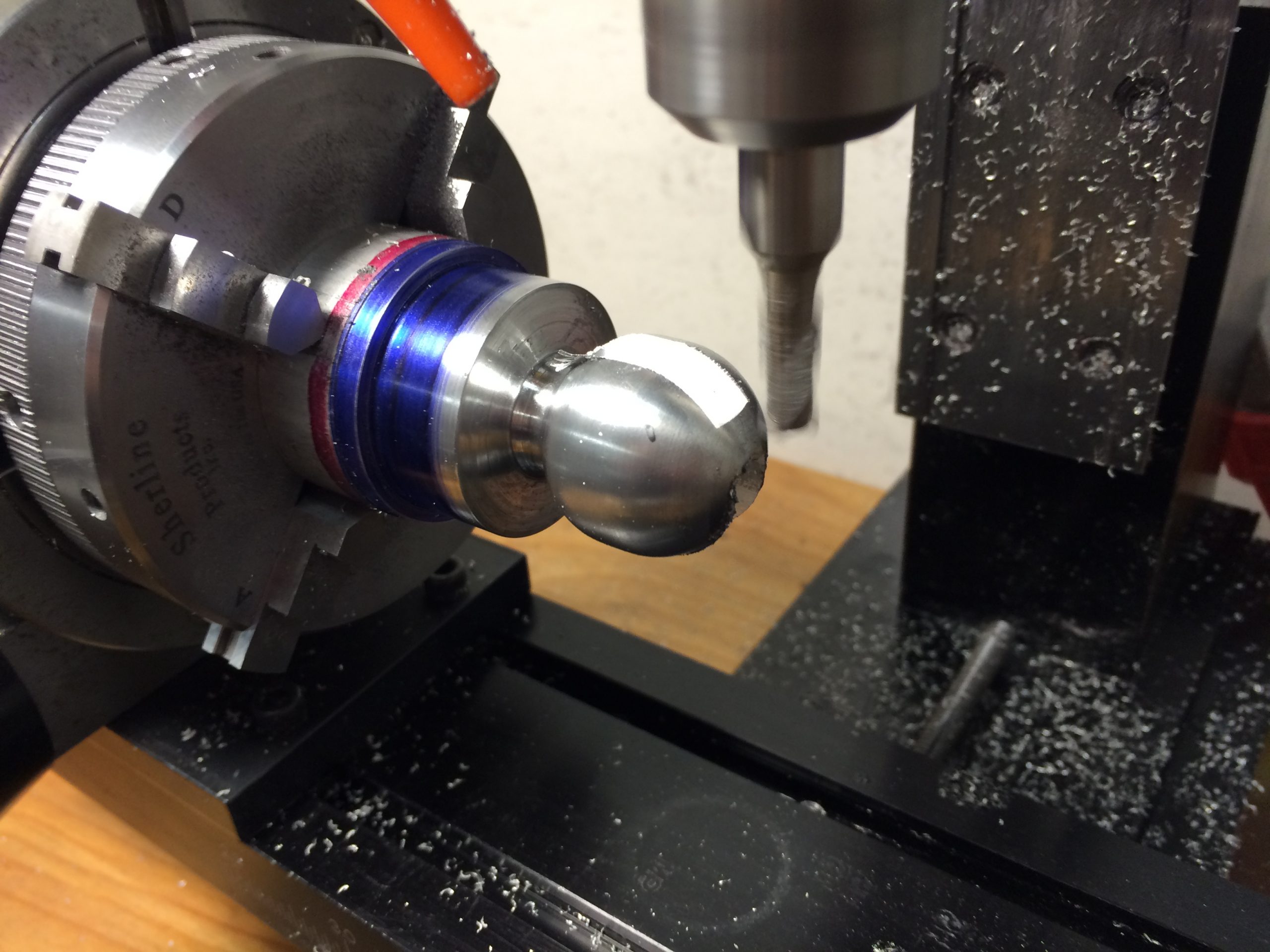


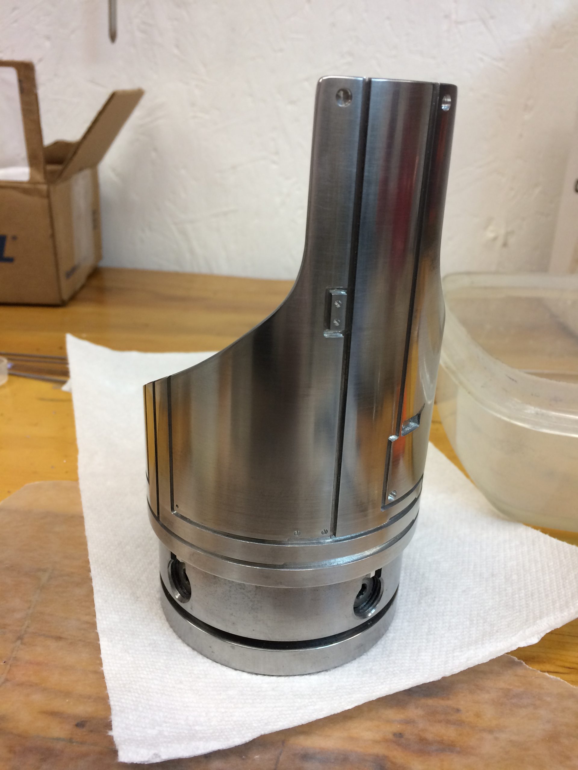
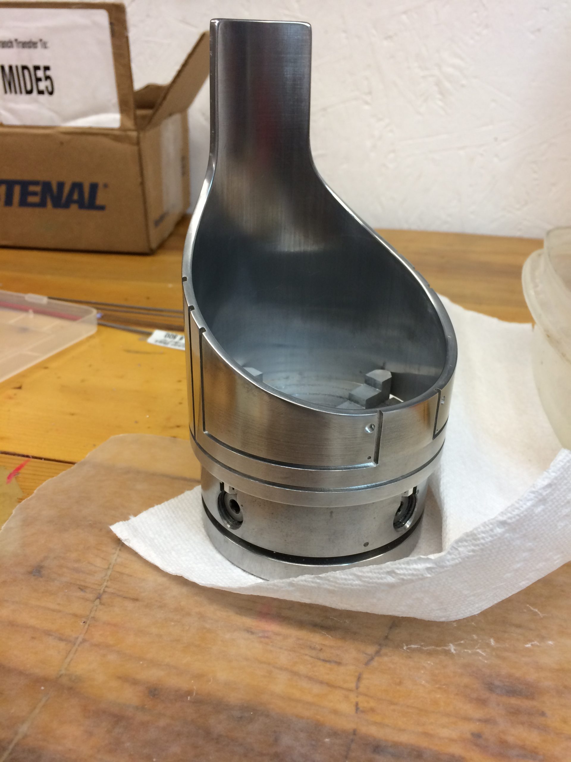
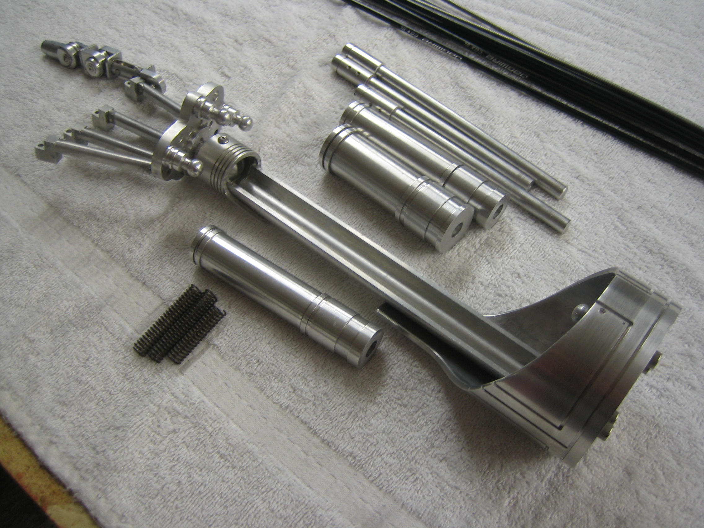
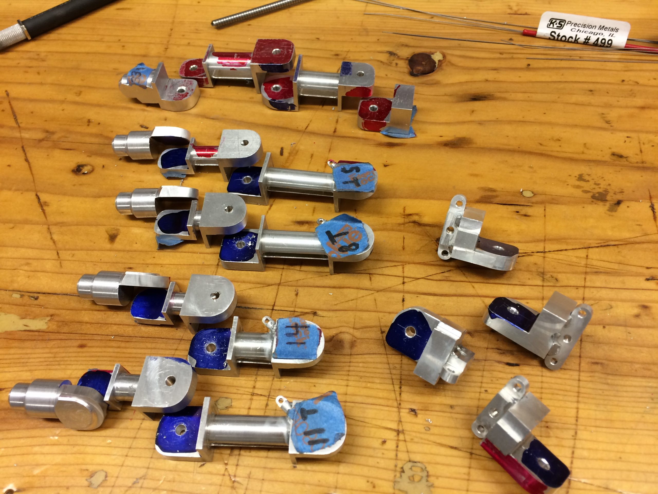
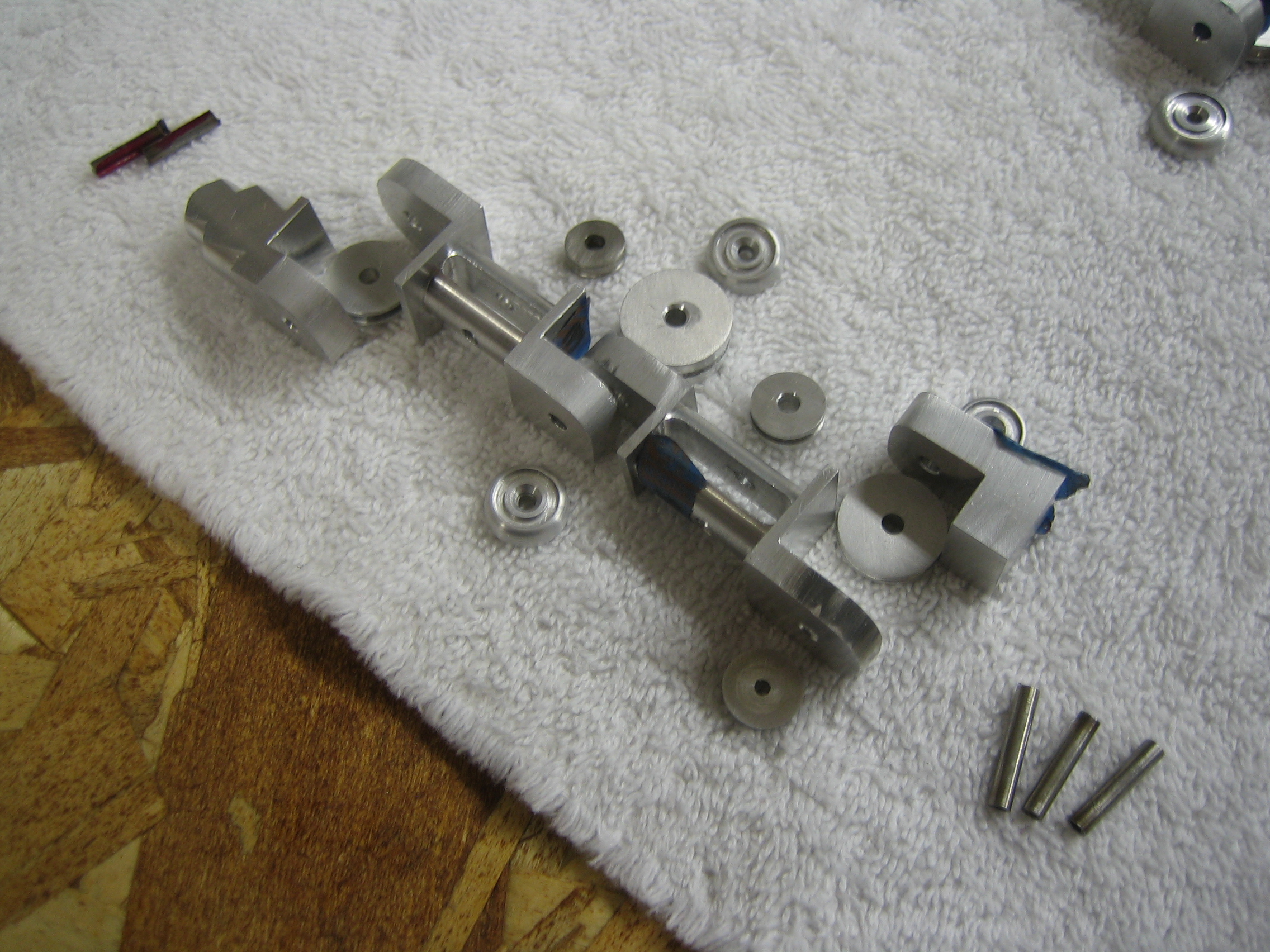

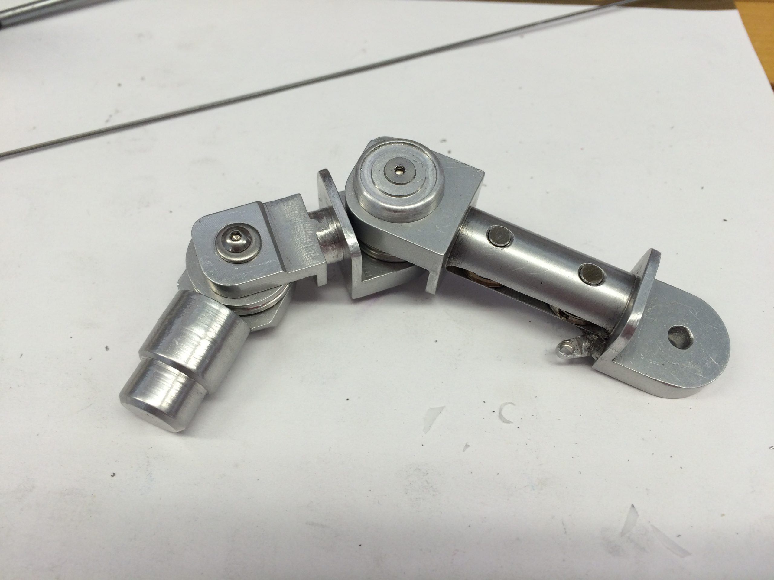
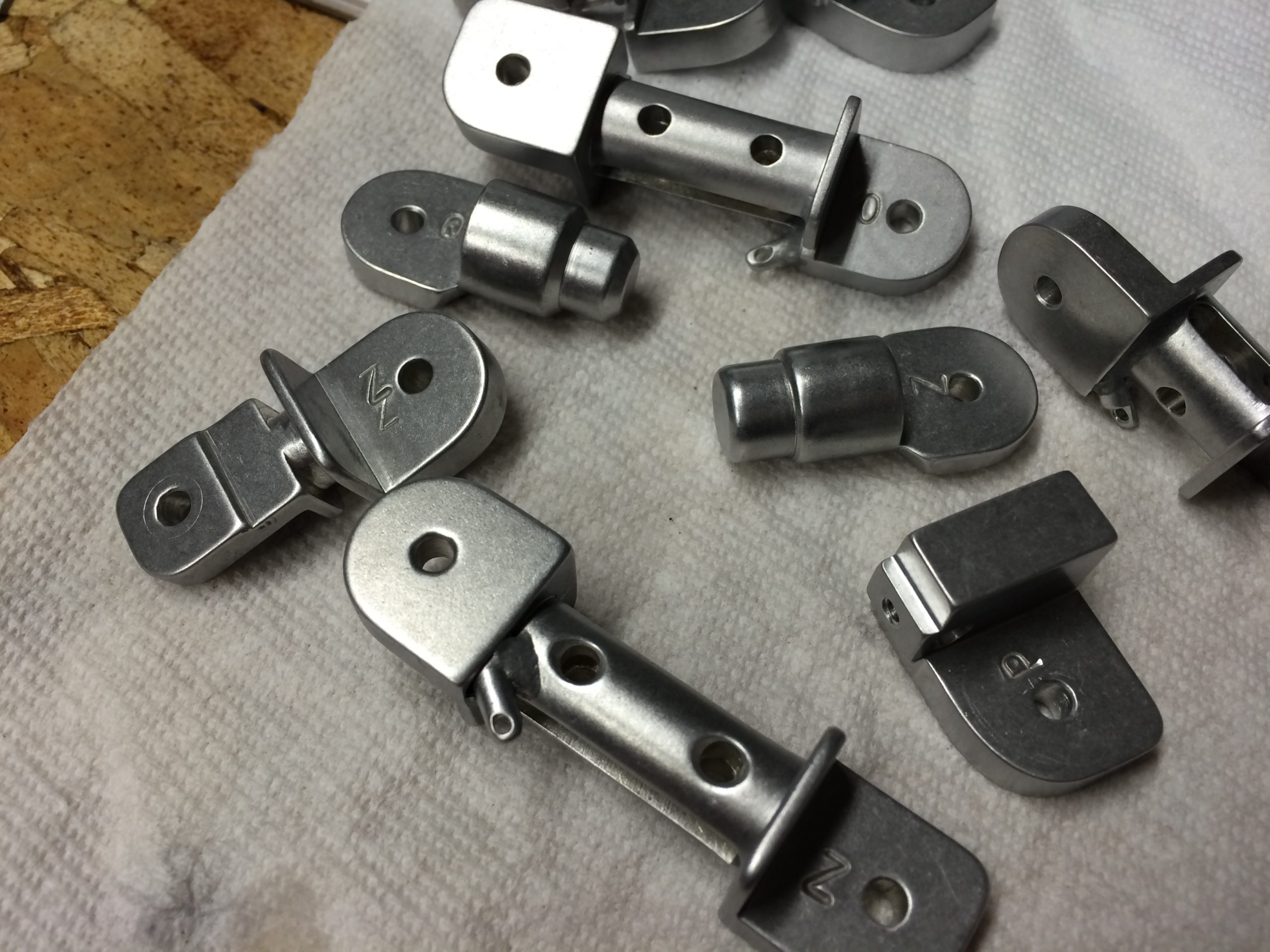
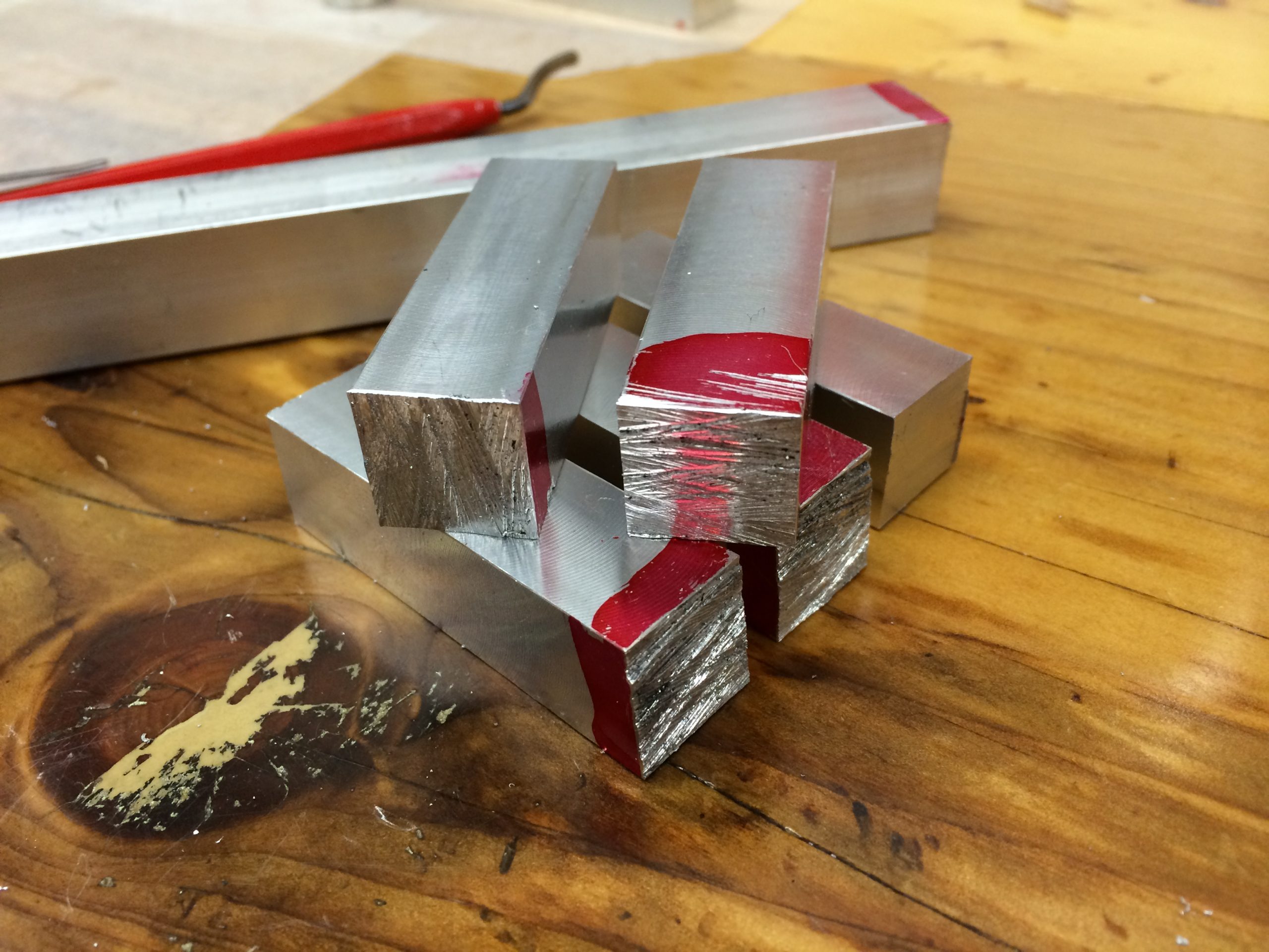
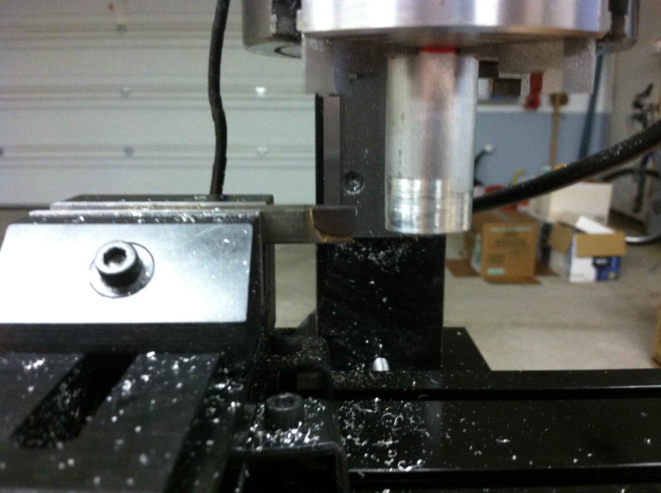


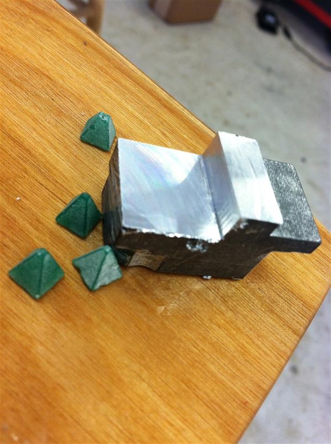
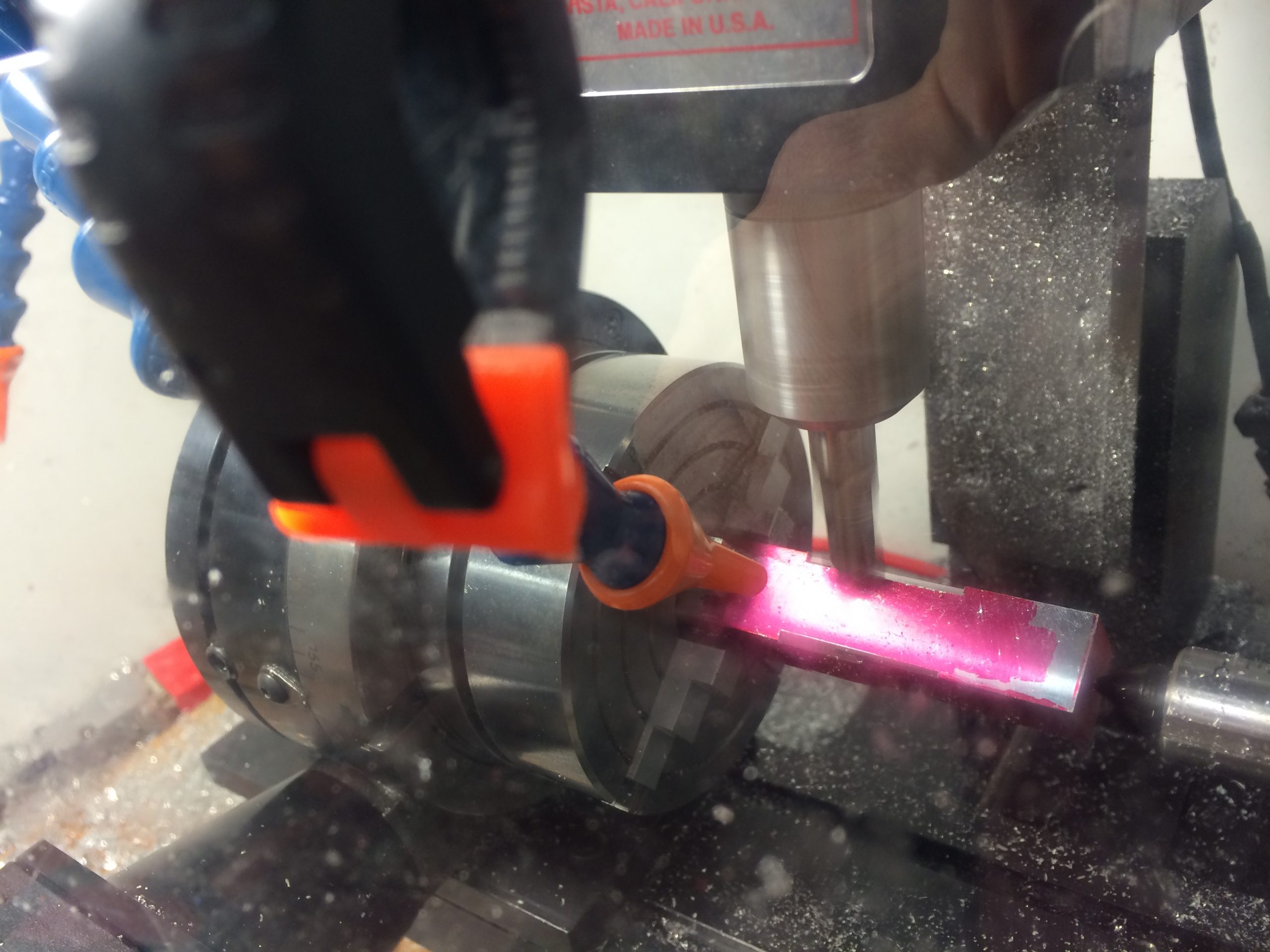
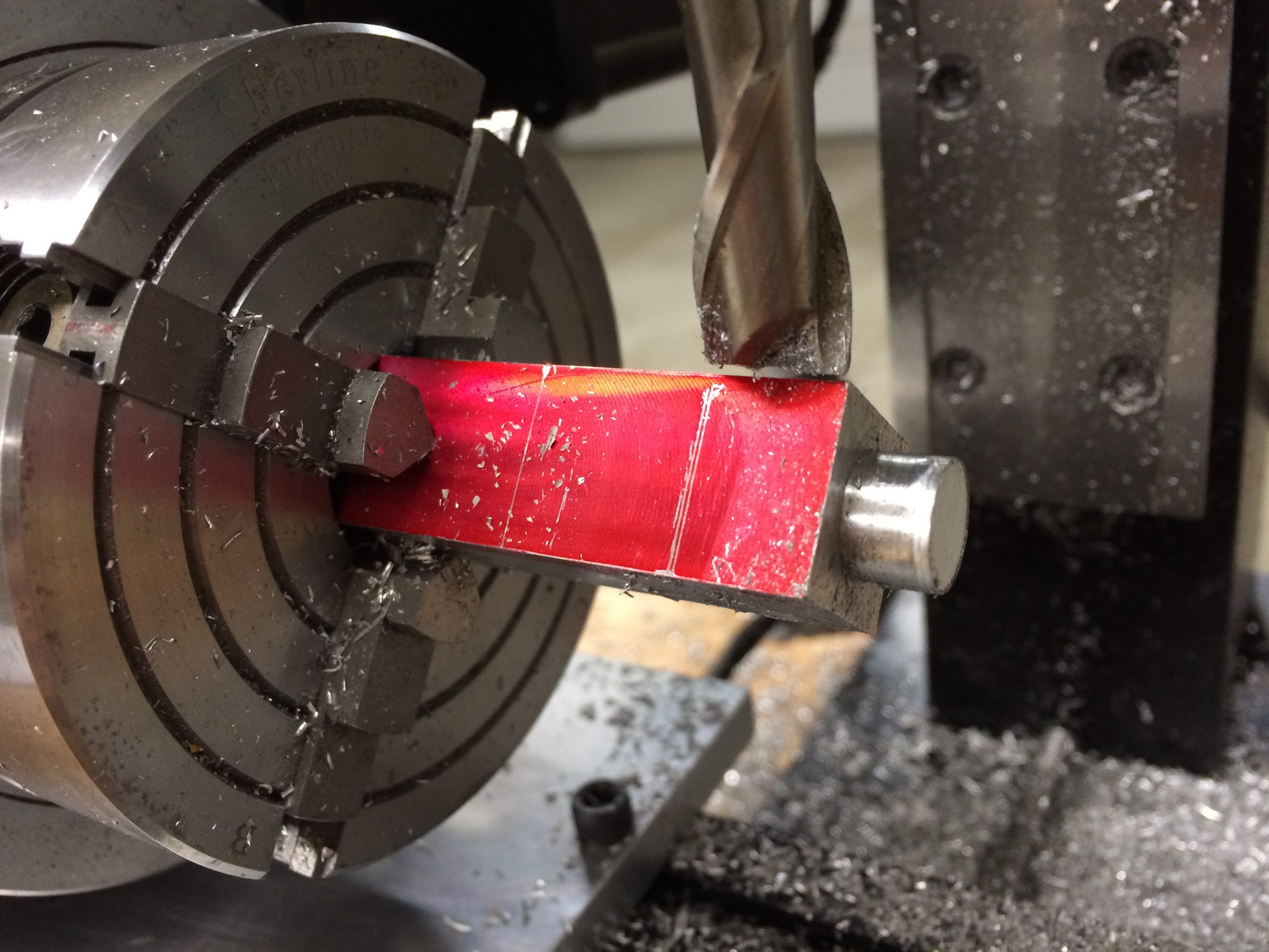
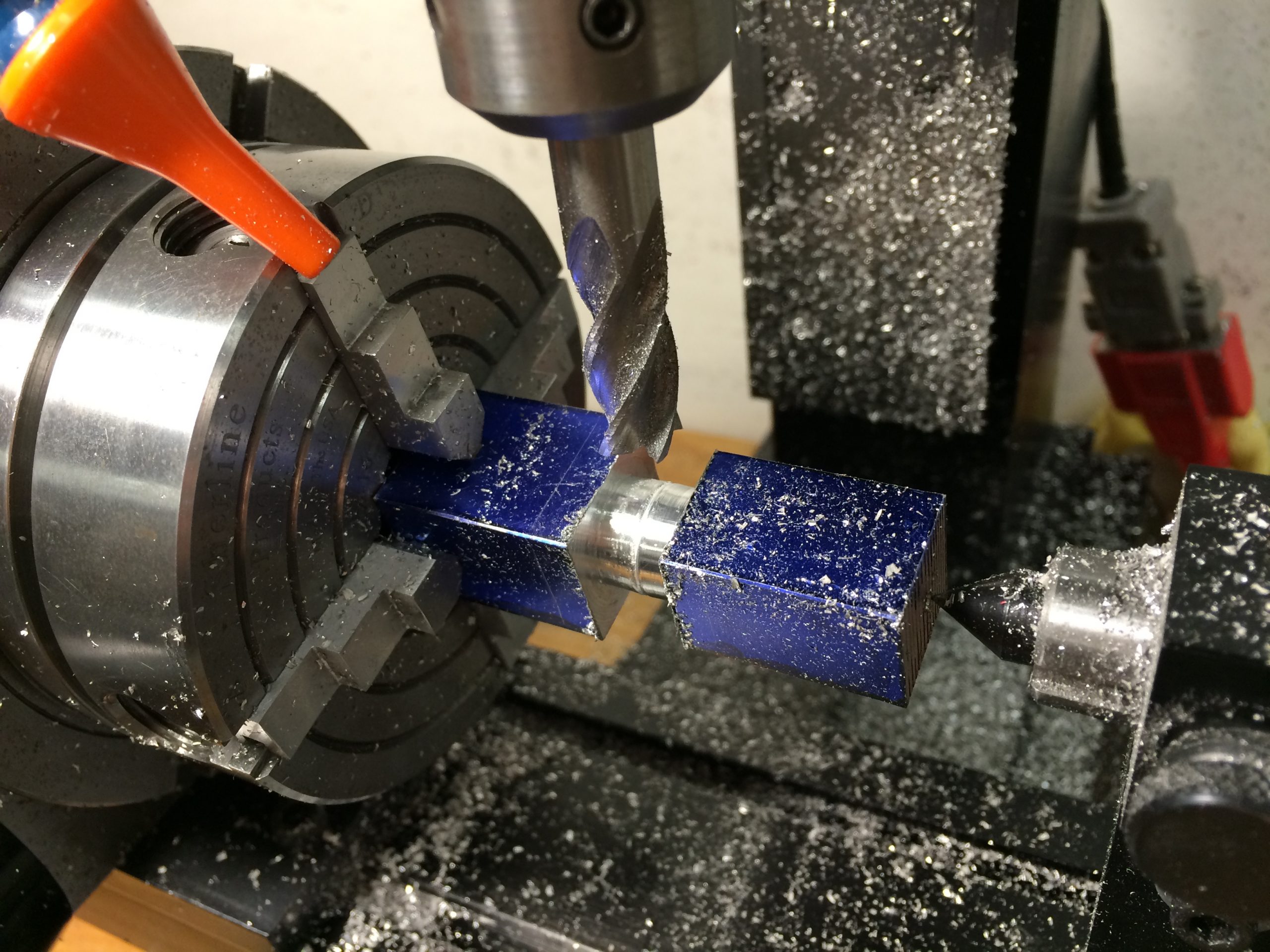
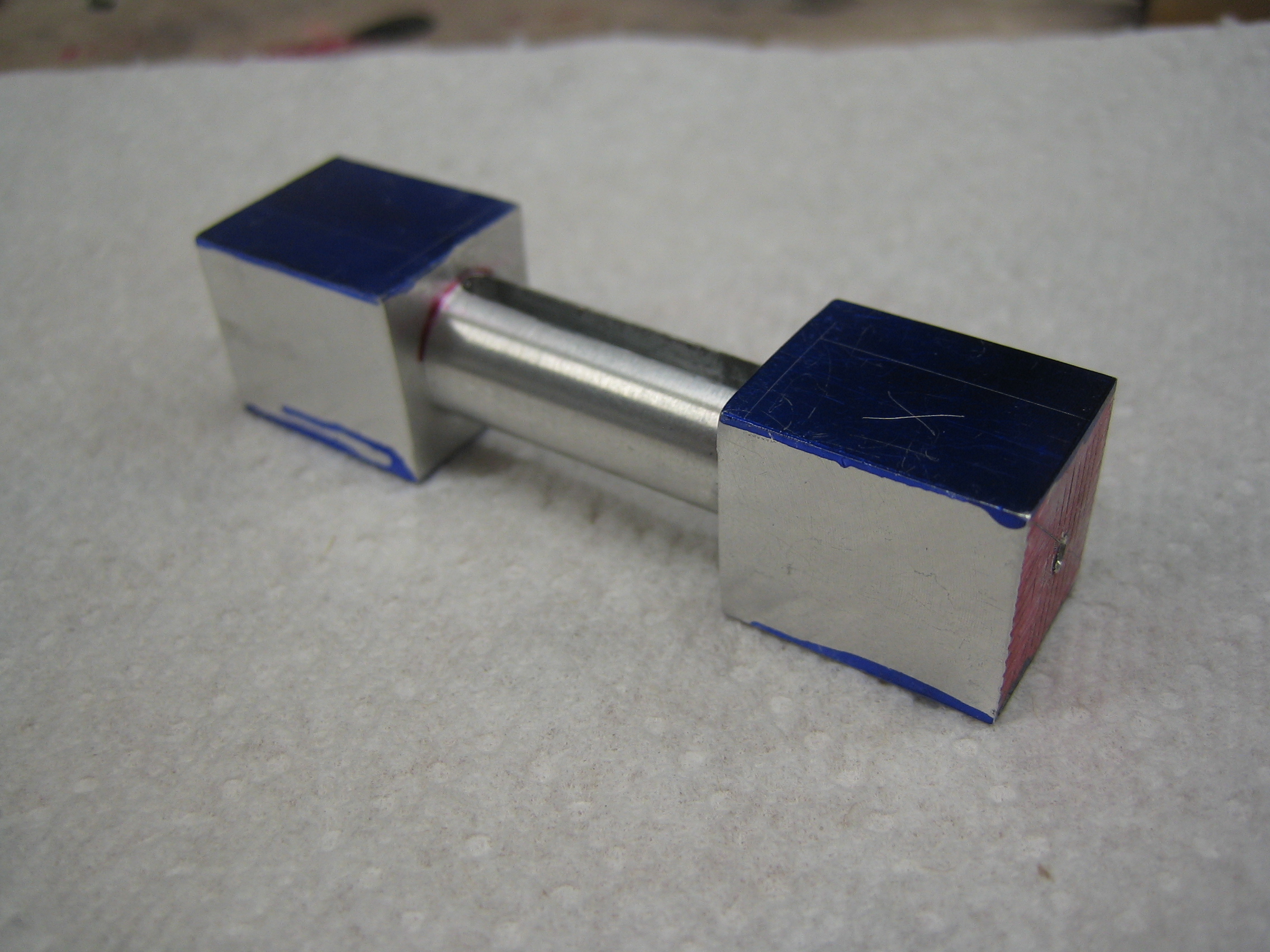
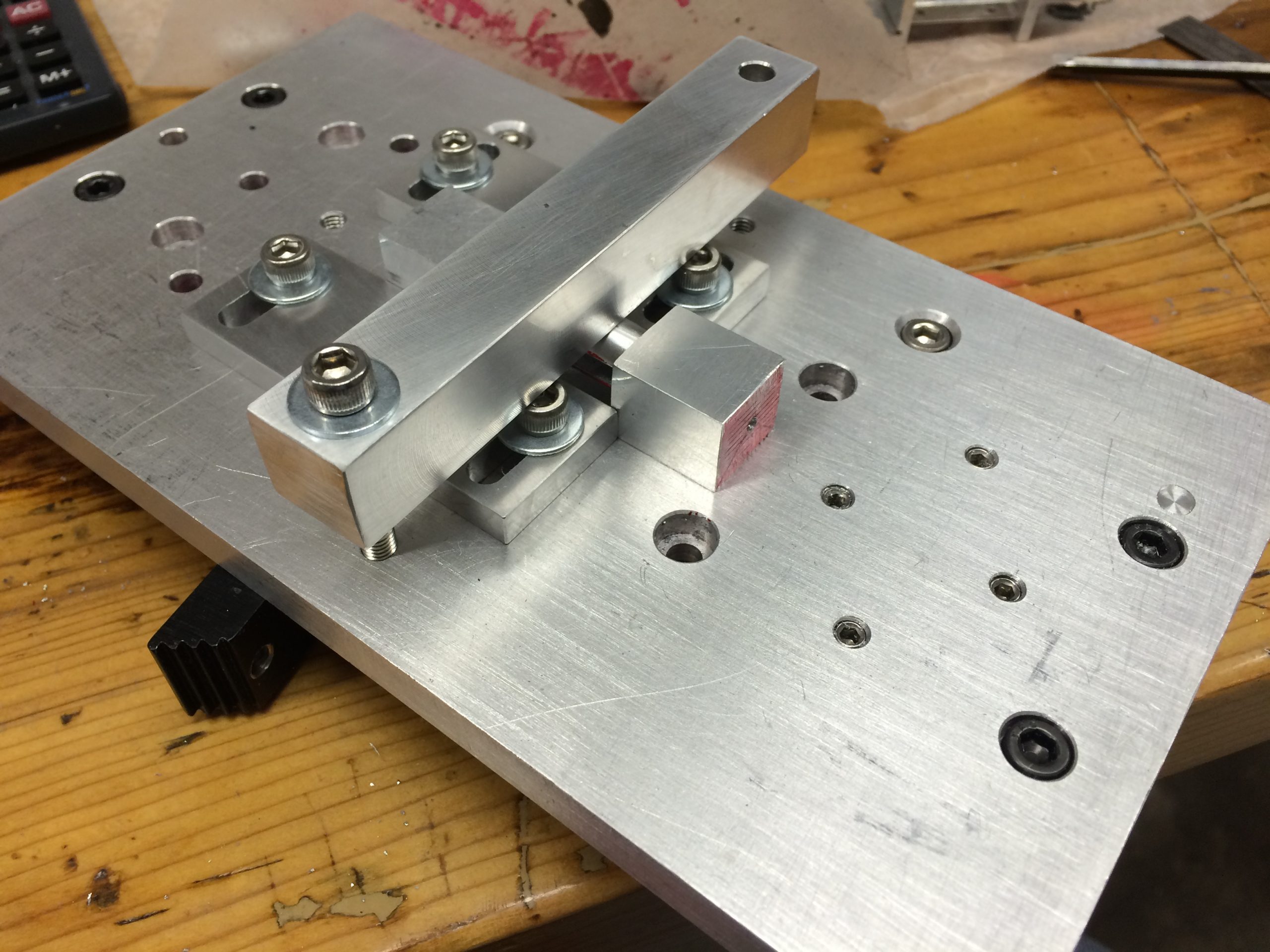
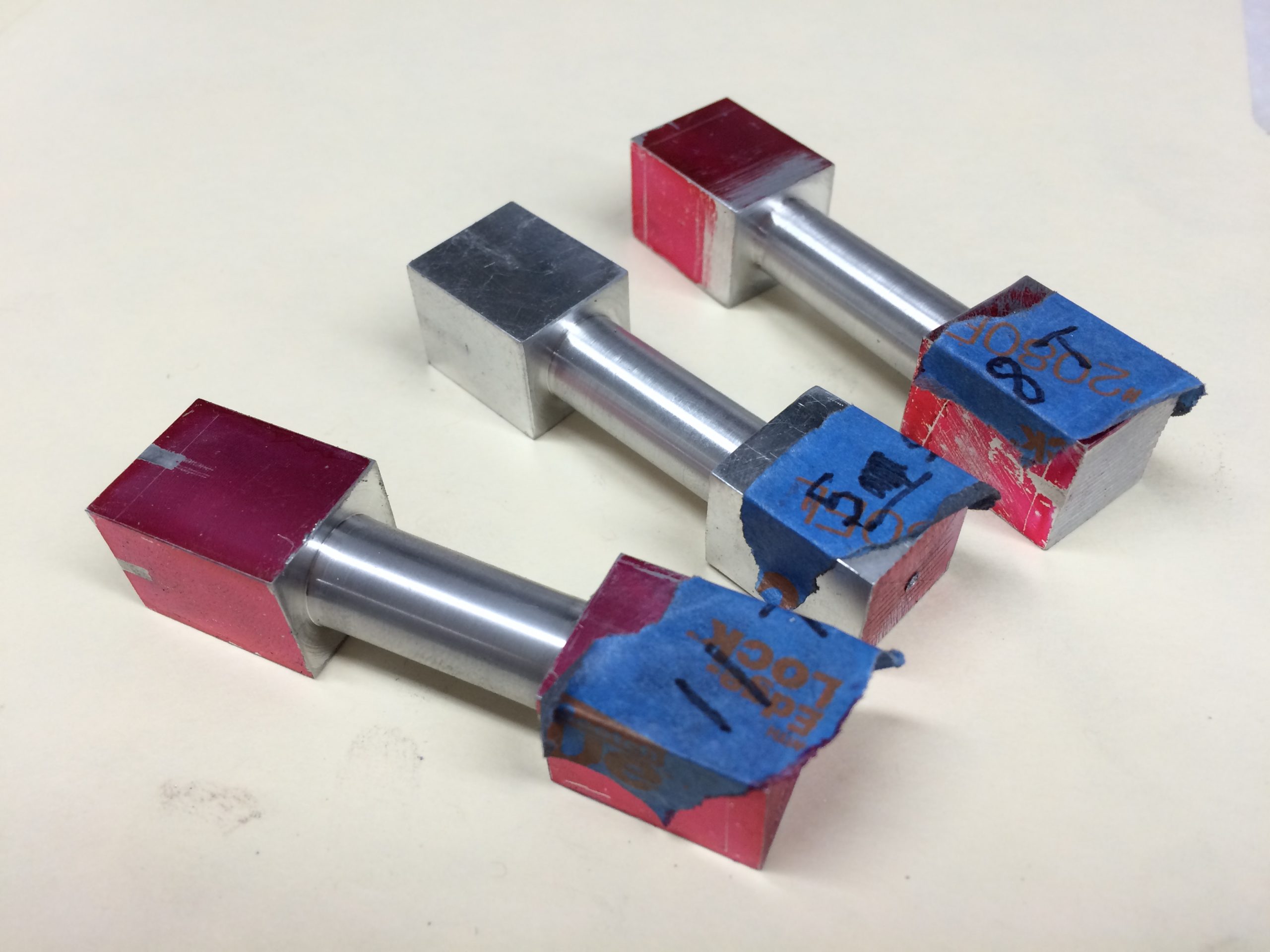

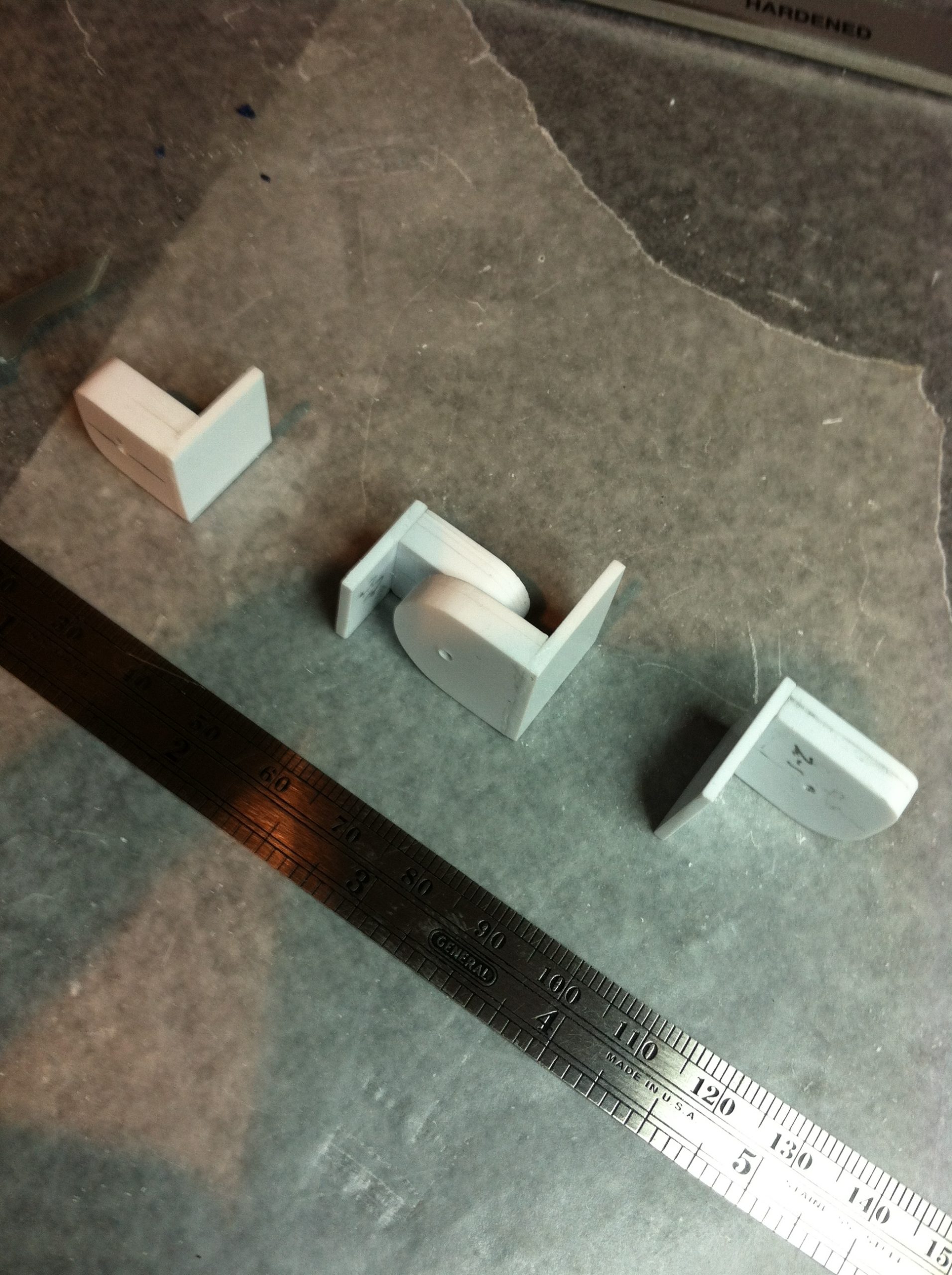
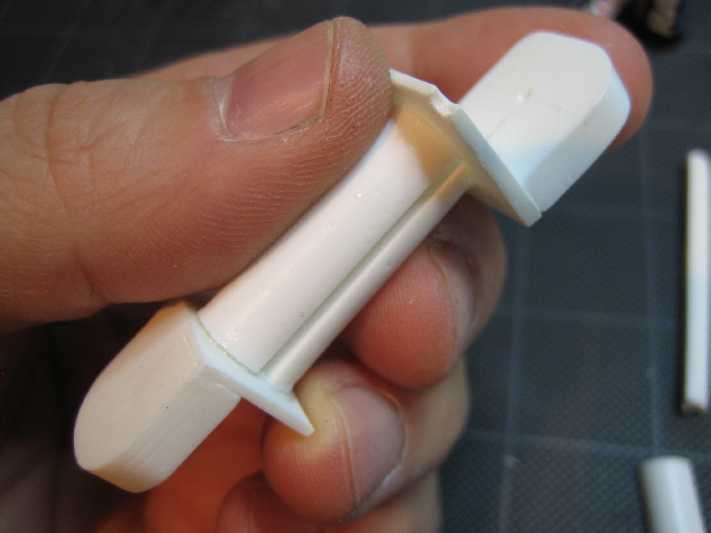


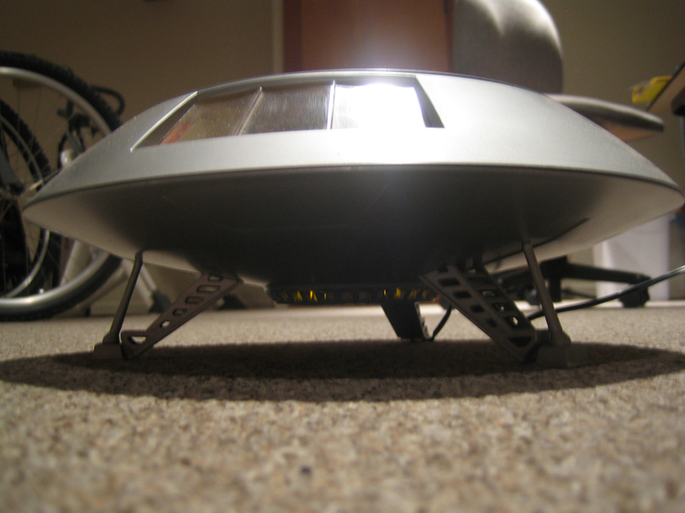


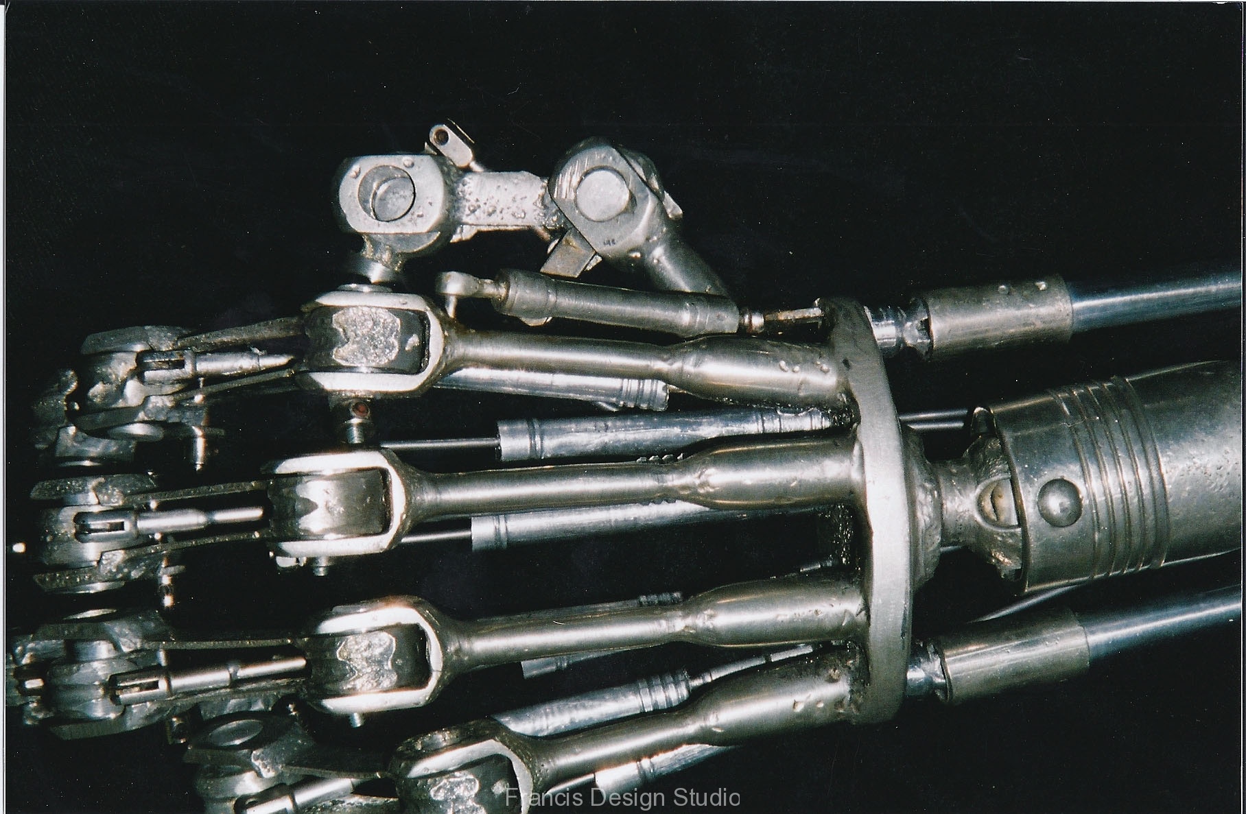
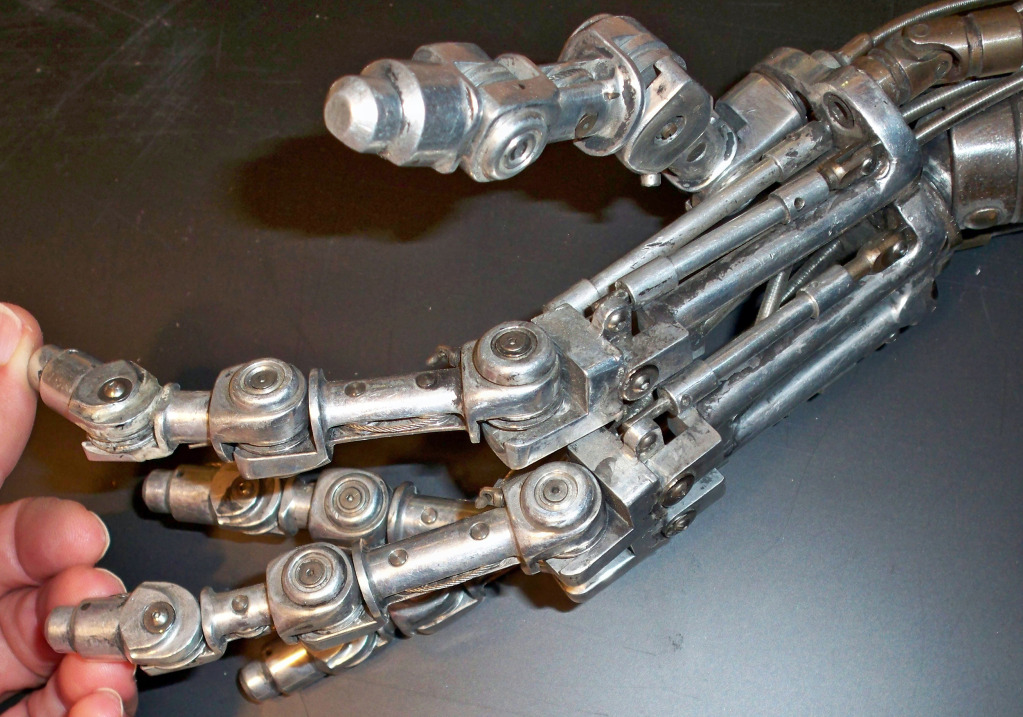
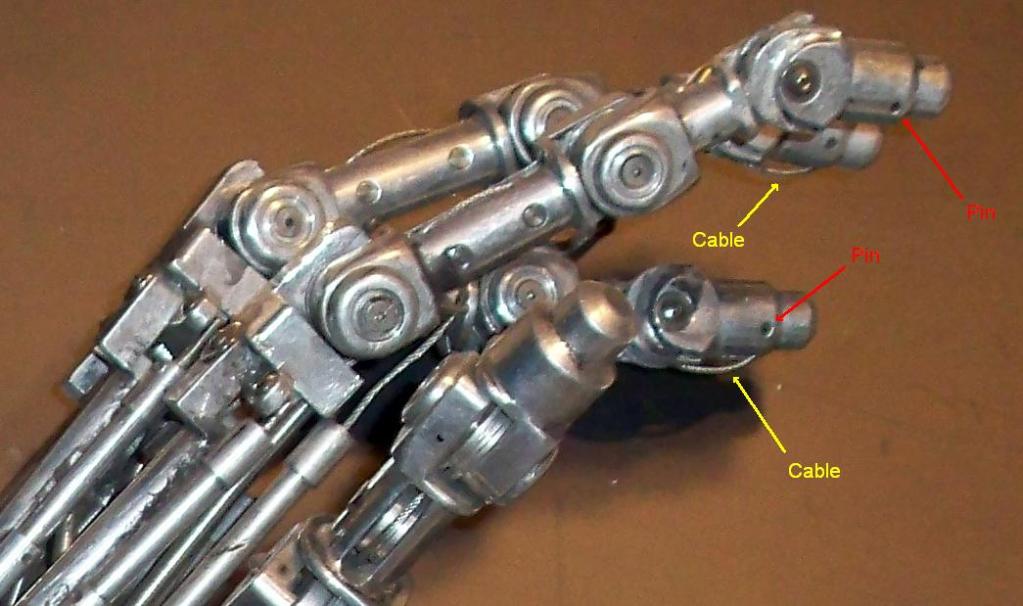
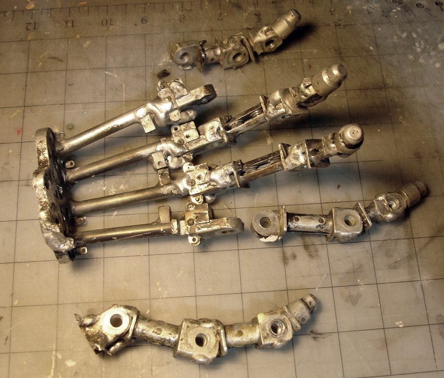
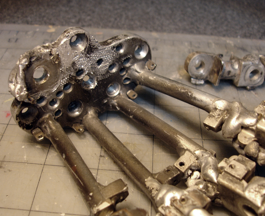
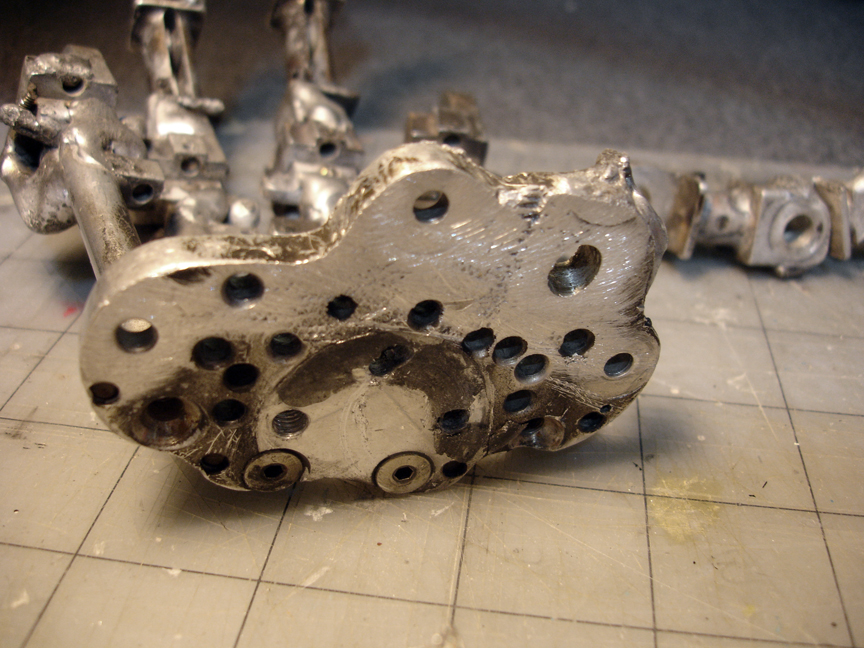
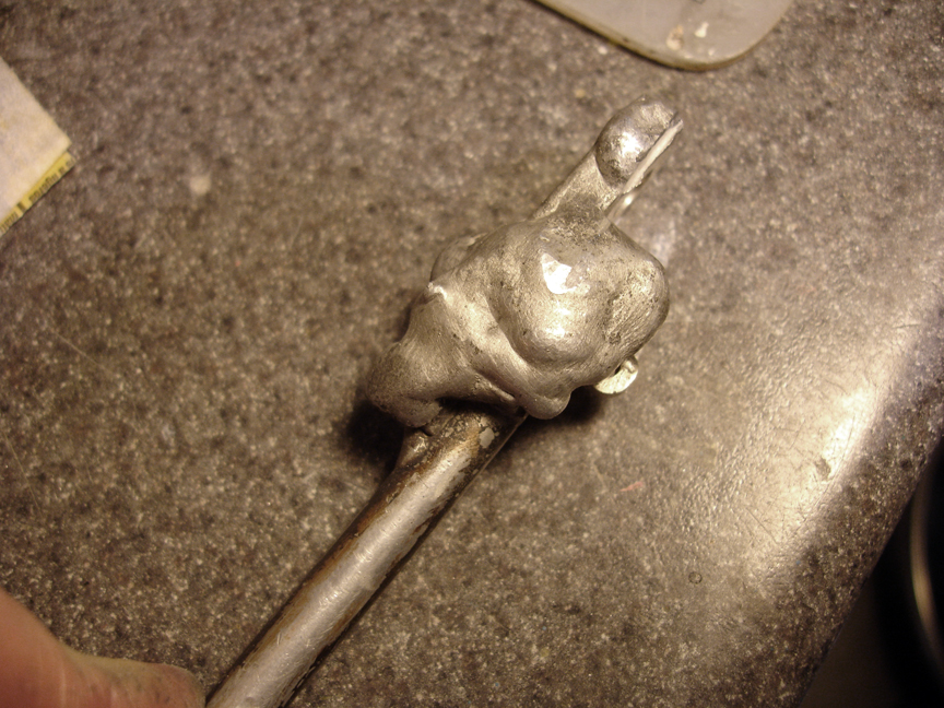
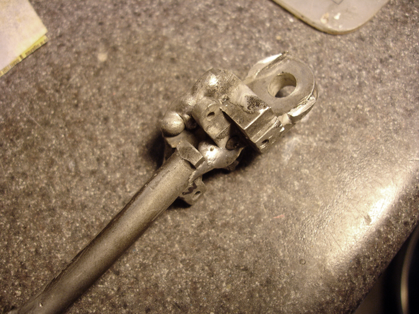
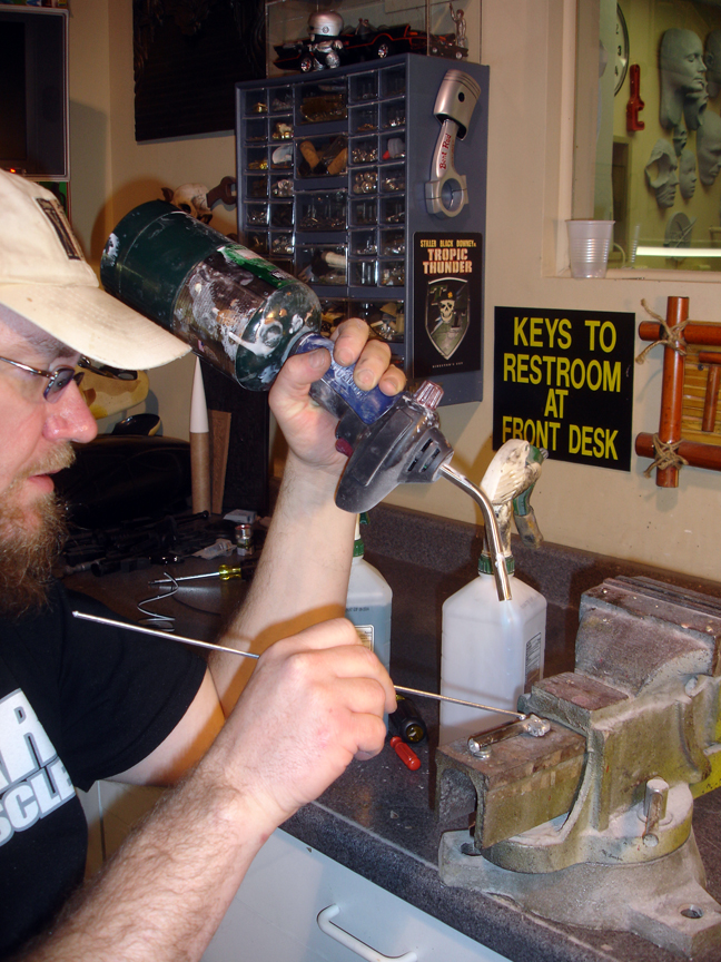
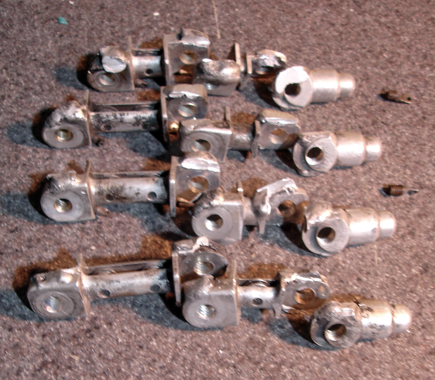
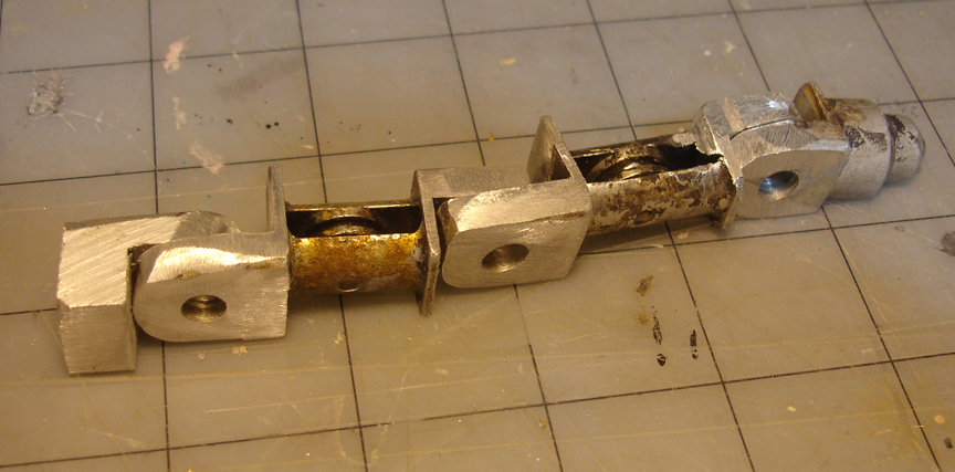
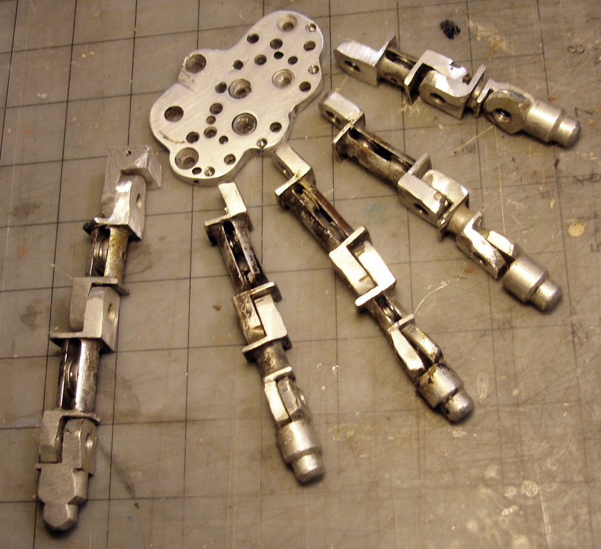
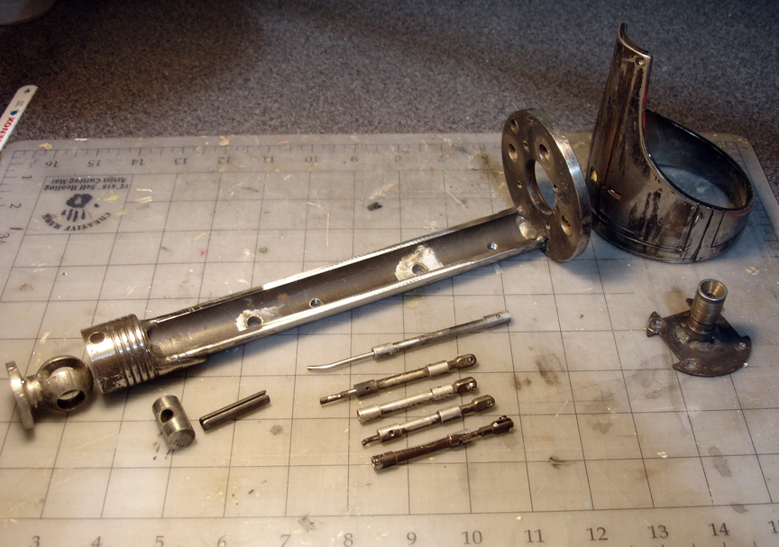
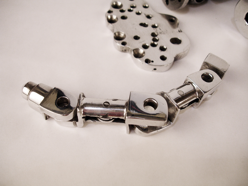
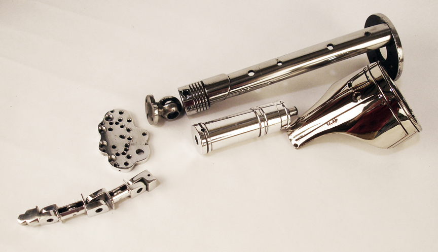
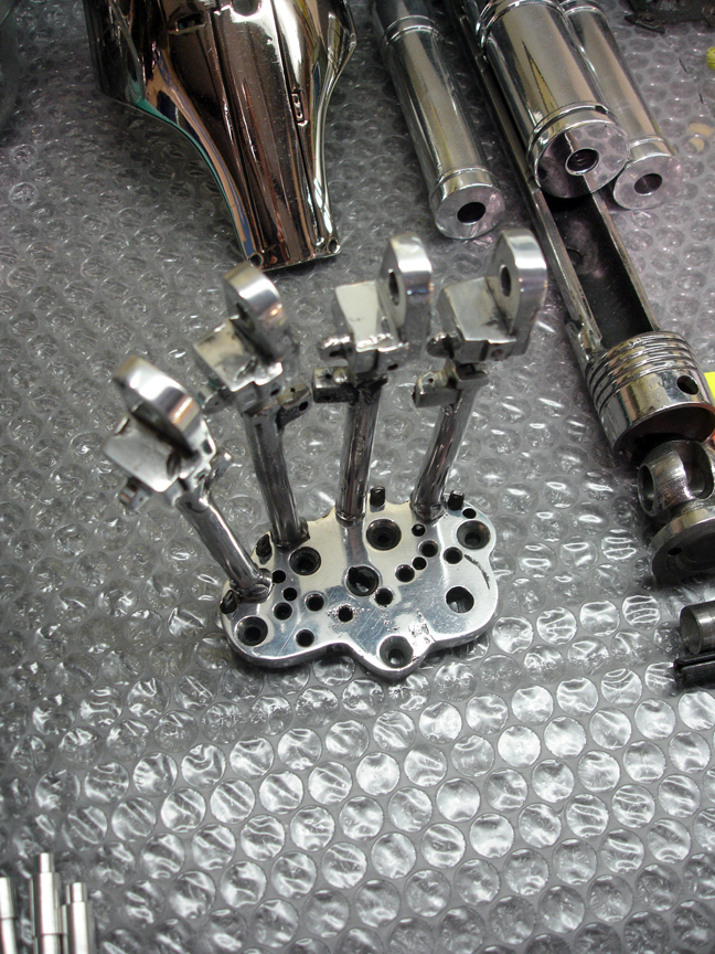
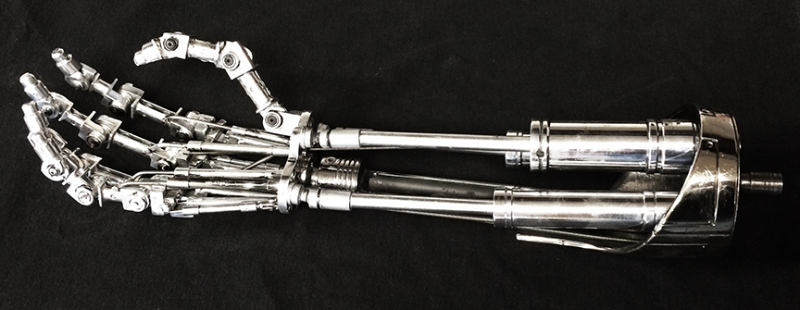


")


")
")

")


")


