Pathfinder started out as a simple CustomTool for my MillDroid application. The idea was to be able to draw a bezier curve,
then generate the G-Code into MillDroid for milling operations.
Like most of my projects, they start out simple and become something much larger.
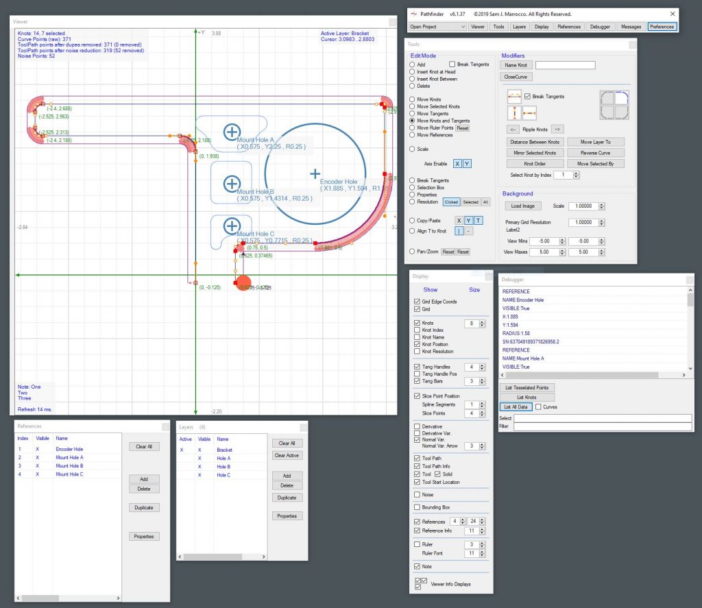
I recalled a lot of old bezier code from a compositor I had written back in my Amiga days. I used my Skeleton Framework to provide a foundation for the application and began the bezier viewing module. The curve viewer grew into a CAD-like window that let me draw, connect, modify multiple bezier curves into complete drawings. More functions came, allowing precision control of every curve’s knots, resolution, insertion, deletion, tangent breaking/control, editing, etc.
This led to visual “rulers” for the design process, and reference shapes for holes and labels.
Now I got crazy: Tools for measurement were added, macros for equi-distancing knots and tangent handles, smoothing existing paths through knots, reversing and mirroring curves, modification to existing knot order and many selection-type tools. The viewer became a virtual graph paper with zoom and pan controls. Drawing Layers became another large addition, then a Properties Form to allow access to the components of every Curve, Knot, Tangent and other items on a low level.
Lots of display tools followed with adjustments for every font, size of text and other minutiae.
This thing had really become a powerful tool for building curve-based drawings and it was a challenge making it. Yes, I know there are pro and free tools out there for curve editing, but where would be the fun of learning in that.
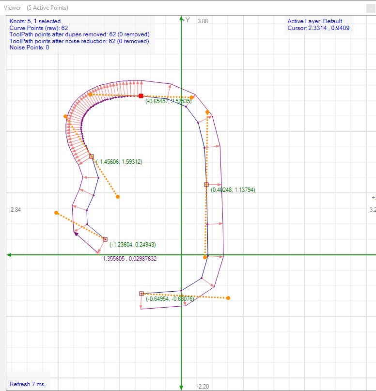
It was now that I came to a realization–That the curves I was generating to represent the path were the CENTER of the milling tool in GCode. Yes, GCode offsets could be incorporated, but I really wanted to SEE the curves in the viewer that the mill would be cutting. This began a learning process about the limitations of offset bezier curves, their paths, vectors and normals. I could now show the path as it was drawn, along with a properly parallel Bezier Curve in realtime. Each normal and vector for the generated path could be seen live. The resolution of the curve points could be adjusted on the fly to make the milling operation for the curve smooth or linear between every point. The tool could be seen traversing the curves and show issues before a cut was made. The GCode could then be output to my MillDroid application.
I learned a LOT on this application and am quite pleased with the result.

