Author: <span>Sam Marrocco</span>

REMEMBER: EXCEL ISN”T AS SMART AS IT THINKS IT IS.

CHECK YOUR WORK

  • Excel Spreadsheet Files can consist of multiple Sheets/Worksheets (these are the ‘tabs’ at the bottom of the screen.
  • Every Cell can have a Formula or refer to another cell by adding an ‘=’ sign first. The formula can be seen & edited above the spread sheet when a cell is selected. Remember to hit ENTER when you are done editing a cell.
  • If you make a mistake in a cell, hit ESC. This will deselect the cell without the changes you had made.

  • UNDO gets you out of trouble. UNDO is CTRL-Z.
  • REDO is the opposite of UNDO. REDO is CTRL-Y. If you UNDO too many times, use REDO to get back to where you where.

  • Freeze the Top Row or Left-most Column by selecting it, then clicking VIEW Menu/Freeze Panes<row or column>
  • Split a spreadsheet for easier viewing by selecting a row or column, then clicking VIEW menu/Split. If you have a Cell selected, Split will split them both, giving you a ‘quad view’.

  • If a Cell contains a FUNCTION (i.e. SUM() , the function’s ‘arguments’ are enclosed within parenthesis, i.e. =SUM(a,b)
  • Parentheses are not necessary if the cell does not contain a FUNCTION, unless necessary because the math requires it, i.e. =(2+3)*(3+4)

  • A Cell’s ‘properties‘ can be edited by right-clicking on the cell. These include
    • Format (changing borders, background colors, text colors, type of text, font and text alignment, and text wrapping.
    • Many of these can be changed ALSO in the HOME menu at the top of the screen. This show a Ribbon with the many of the same items.

  • A NOTE can be added to a cell by right-clicking the cell, then selecting Add Note.

  • To DUPLICATE many rows or columns of a similiar function, select all the row(s) or column(s), CTRL-C (copy), then past the new rows or columns where you want and hit CTRL-V (PASTE). This will duplicate the rows or columns and ‘ripple’ the formulas in the cells accordingly.

  • Don’t forget to SAVE the spreadsheet when you’re done. Save with a number on the end of the name to save a new one and not delete your old spreadsheet.

Cheat Sheets

After I began to use my Sherline lathe in earnest, I started to appreciate the amount of time that went into switching the tooling involved in turning operations. There were a few options available for quick change tool posts, or QTCP abbreviated. Sherline makes one that seemed very overpriced, required wrenches to change the tooling, and just didn’t seem like it was worth it. AtoZCNC made one, but I read about a lot of holding issues and they always seemed like they were on the verge of going out of business (they did). Since the Sherline is tiny, most other QCTPs didn’t git. I had read a lot about an older ‘pillar-type’ toolpost that larger lathes used many years ago. The style doesn’t seem to be very popular today but it seemed like a very sturdy design so I decided to make one.

I read a lot of older machinist’s designs and downsized it to fit my lathe. I’d make a bunch of spare toolholders because you can never have enough of those. I would also make two tool posts: one for the standard Sherline Lathe configurtion, a taller second post for when I use the Sherline headstock riser for working on larger items.

I picked up some two-inch square 1018 steel bar stock for the tool holders and two-inch diameter 1144 Steel Rod for both toolposts.

I turned both toolposts, feeling guilty about turning away so much steel, but without a welder I wanted the stability of the base and the post being a single piece. I then used my mill to square up the base.

The finished taller toolpost. I beveled all the edges and drilled and reamed the center hold for holding it to the base of the lathe.

A finished tool holder. In all, I made 12. Some for 1/4″ and 3/8″ tooling, boring bars and others purposes.

I used a 7/8″ hole saw on my drill press to rough out the center opening, then a bandsaw to cut the compression slit. My mill and a boring headwas used to cut the center opening to exactly the correct size to slip onto the tool post. The clamping bolt holes were cut on the mill and hand-threaded. I ‘polished’ the final pieces under water on my wet-sanding/lapping rig (see elsewhere in this blog for details), then immediately upon drying oiled them to prevent rust. I use a local foundry to do my heat-treating to temper/harden the steel for final use. For 10 dollars a batch, it isn’t worth the price of installing my own heat treating oven.

A nice close fit on the toolpost.

The first half dozen, before I realized I should make more. I turned two brass knobs for each toolholder, knurling them for ease of use. These made locking height adjustments for more accurate tool changes.

They came out perfect in concept. However, in practice they have a few flaws:

1-The toolholders are a BITCH to make. It takes a lot of time and effort to remove all the one inch of steel from the center of each one and bore them perfect.

2-The base had a tendency to pivot. This was fixed by milling out the bottom, but it really needs a plate along the edge of the lathe carriage to prevent it from pivoting. Cleaning the base before clamping helps a lot.

3-The toolholders have a tendency to pivot around the center of the toolpost when cutting aggresively. Again, cleaning the post helps, but it is a fundamental flaw in having a round post.

I still use them, but I have since moved on to a wedge-style OXA-sized QCTP.. It was a worthy challenge, but the advantages of the OXA offset the issues with the pillar-type QCTP. Because of the Sherline’s small size, I had to make some adaptations to the OXA style toolpost such as a custom base to keep it at the proper height. I also added a second arm/knob to eliminate the need for using a wrench to lock it down. Overall the OXA was a better choice.

Quick Change Tool Post for Lathe

The MillDroid Pendant is a handheld/desktop controller box that provides physical buttons and a jog wheel to my MillDroid CNC sofware. It cuts down on the amount of mouse and keyboard used for positioning and operating my CNC mill and lathe.

I designed and built the pendant to access my KFlop-based MillDroid Controller hardware via a 25 pin cable. I based my job wheel/encoder reading software on some that was included with the KFlop hardware. Once modified for my own use I added the montoring code for the buttons and communications with my main app. Global variables are shared between the KFlop hardware and my VB.NET-based MillDroid application and it is through these variables that the apps communicate with each other by the sending of variables that they both monitor.

The case was built from 1/8″ styrene, ‘welded’ together and reinforced at all the joints for strength. Styrene is easy to mill once you get the feeds and speeds correct to prevent melting. Nice chips that clear with compressed air and no lubricant is required during cutting. I cut at a steady pace of 8 inches per minute, a .04″ depths of cut and spindle speed of 1500 RPM using a 1/8″ end mill on my Sherline Mill.

It took a couple hours of work cutting all the pieces from styrene, sanding then gluing it all together.

The internal wiring took considerably longer. I like to label every wire and document all my work for later review. Too many times, I’ve come back to a project I built, looked inside and thought “what was that idiot thinking when he did that?”. Since I document my hardware, software and every project, there is never any doubt when I open something I had previously built years later: I always know what that idiot was thinking when he did it.

The design it relatively straightforward. A few switches needed pull-down resistors because not all of the KFlop’s IO pins have them by default. Simple enough to add a few where needed. I wanted the pendant as small as possible so I tried to keep all the smarts outside of the pendant. This meant a few more wires externally but they all fit in a 25-pin printer cable with a a few to spare. I even had enough for another shiny red chrome abort button.

Shop Projects MillDroid Pendant

A little history first….

Sometime around 2010 a woodworking blog revitalized the use of the Joseph Moxon Twin Screw Vise. Originally published by Moxon in “Mechanick Exercises” in 1703, this is an engraver plate of the device….

Since that 2010 article there has been a large resurgence involving the use of this vise, with kits becoming available at several woodworking establishments. Since I needed a better woodworking vise, this seemed like a good project that would utilize a variety of techniques…..and I was sure I could come up with some method of making it more complex than it looked.

A little googling reveals hundreds of designs from woodworkers around the world. I perused ever single one of them and after digesting it all picked and chose the qualities that I wanted for my own design.

I knew that I wanted the vise wide enough to handle 24″ wide planks. I also knew I did not want the usual vise “bar-type” handle. A hand wheel seems like a much more elegant method of controlling the jaw. Metal hand wheels abound, but I stumbled upon another woodworker’s design in which he had made hand wheels from several differing species of wood and I fell in love with the look–plus it made the wheels very difficult to make and that made it a nice challenge. Mitch, I thank you for the inspiration that your design provided!

I obtained some 2″ thick hard maple for the main body and used Maple, Cherry and a neighbor-provided piece of mahogany for the hand wheels. A trip through the band saw to re-saw down to proper thickness into manageable planks.

Using metalworking angle blocks on the band saw I was able to make some precise cuts of the stock into the building blocks I would need for the hand wheels.


Some of my stock was different thicknesses. This would come back to haunt me later.

Gluing blocks together carefully as to keep the grain of each block in the same direction. To keep the pieces flat I clamp them on a scrap piece of MIC-6 Aluminum Sheet that I use for other projects since it is about as flat as flat can be.

My plan had been to run the completed pieces through my jointer to flatten the remaining side. This is where I made a critical error, forgetting that the jointer would flatten, but not guaranteed that the newly flattened side would be parallel to the previously flat reference edge. What I really needed was a planer, but I don’t own one. Dumb, Dumb, Dumb. The pieces were off enough that I knew I would see the edge design “wobble” as the wheels turned. So I decided to re-cut everything and start over……better take a break and work on……

….cutting the 8 spokes of the hand wheels from cherry with a coping saw. I really need to be a scroll saw one of these days, but hand tools are therapeutic.

Rounding the cherry bases on the disc sander.

After re-cutting and assembling the new ‘pie slices’ of the hand wheels, they became the “bread” in a sandwich with a filling of 1/4″ walnut. It gives them a nice stripe around the wheel’s outer diameter.

I didn’t save any pictures of it, but my new method of “planing” the disks to the same exact thickness involved using my metal working mill. It’s a small Sherline, but I was just able to fit the project into its working envelope.

The left was an earlier, crappy attempt. The cutter on the edge was my second, better version and worked perfectly. No rake, a large radius and plenty of clearance for chips.

On my grinder, I ground a piece of high-speed steel into a large radius fly-cutter, then used that to ‘plane’ the surface of my newly re-constructed hand wheel disks into exact thickness prior to glue up.

See why I need a better vise? Although you aren’t supposed to chisel in a Moxon because it isn’t designed to put those types of stresses on the thread rods.

A good amount of chiselling with a mallet to carve out a place for a large hex nut in the wheel bases. Similare square holes were chiseled into the base of the vise for the other end of the rod. The nuts, both square and hex, match the characteristics of a 3/4″ Acme threaded rod that I would use for the vise. I wanted Acme rod instead of a normal threaded rod because of the accuracy of the machining that would give it smooth movement and less backlash. I bought 36″ inches with plans to use the rest for something else, and only needed 18″ for the vise. I cut the Acme into two 9″ pieces with a hack saw manually as my grinding wheel wasn’t large enough without risking damaging the rod. Heck of a good workout cutting 3/4″ steel rod with a hacksaw, even with lots of cutting fluid. I think I put an inch on my biceps making those cuts.

Don’t forget to break out the magnifying glasses and hand file any spoiled threads from the cutting process. This steel was pretty hard stuff.

Alignment of the Acme threaded rod into the handwheels would be critical. If it was off a tiny bit, the hand wheels would wobble when spun and vibrate. I made a simple jig from MDF with holes large enough for the rod to hang through with room to spare. I place small wood angles as shims under the corners of the MDF board and used my precision machinist level to make certain the board was level in two dimensions. Now the Acme rod goes through the nut, which is placed into the hand wheel base with 30 minute epoxy. By setting the base/nut/rod combination through the hole and letting the rod hang down, gravity will cause the rod to act as a plumb line, pulling it perpendicular in two axes to the previously leveled MDF tabletop. Within the wood base, the nut is sitting in a little pool of epoxy, giving a a little “wiggle room” in which to pivot. Because I didn’t trust gravity, I also broke out my precision machinist square and verified that the rods were indeed hanging at exactly 90 degrees in two axes. I knew it would work….really šŸ™‚

All the other hand wheel parts were hand sanded and scraped into shape. The ‘gravity jig’ was again used to let the weight of the acme rod hold the spokes, base and wheel together for glue up.

I figured I needed to keep the handwheels from scraping the vise jaw to I made a couple stainless steel washers from 2-1/4″ SS rod. Stainless is tough to machine and drill with smaller machine tools but it can be done. Slow and steady wins the race, plus it was worth it to help minimize rust potential with the stainless.

That is a lot of maple. Thick maple.

I had recently purchased several japanese pull saws and wanted to learn to use them properly. This was a good project for it, and I now prefer them to the typical western ‘push’ saws. It takes a while to get used to the reversed cutting direction as does handling the thin blade, but the thinner kerf seems easier on the muscles. The technique takes a bit of getting used to for certain.

Don’t worry, that’s only a shadow on the wood.

I tried initially to cut the inside curves with a Forstner bit but this burned the maple. It then became an tedious excercise in using the coping saw and sanding. Did I mention I need a scroll saw?

I uses a series of boards and clamps on my drill press to align and drill the 3/4″ holes in the jaws. The Forstner burned the maple again but I got through it by cooling the bit between passes.

The front jaw holes were widened in the left-right direction by 1/8″ on the exterior of both sides. This would allow the front jaw to ‘rack’ when tightened and allow non-square items to be held tightly. This should provide about 1-2″ of non-parallelness in the item being clamped.

I used my (newly) standardize finishing chemistry/technique for the entire vise and handwheels. The process was…

1-Scrape or sand everything with ~220 grit. Blow out all the dust with compressed air.

2-Wet everything with distilled water (to avoid contaminates) and let it dry for a several hours to raise the grain.

3-Scrape or sand the newly raised grain with 220 grit.

4-Get rid of the dust again with compressed air and wipe with mineral spirits. Let dry for several hours.

5-Soak with a saturated rag of Danish Oil (Watco works for me). Spend about 5-10 minutes keeping the surface of the wood wet until it won’t absorb any more or 10 minutes has passed. Any longer and you risk the oil getting thick on the surface and you’ll have difficulty removing it. After the 10 minutes has passed, wipe off all the excess. Make sure you get it all and wipe it *hard*.

6-Let the Oil soak in and dry for at least 3-4 days (depending on humidity and temperature) since I’m going to topcoat it.

7-Brush on General Finishes Arm-R-Seal, which is a oil/eurethane resin, then wipe it lightly off. Let dry 24 hours minimum, then lightly sand off any dust/bumps with 600 grit sandpaper. Repeat over three days to get three coats. Don’t sand after the last coat, but use a brown paper bag and buff out any dust bumps.

8-Let the topcoat cure for several days to maximum hardness before putting weight on it.

….and behold! My new Moxon Twin-Screw Vise.

Moxon Vise

A sidebar here with some of my thoughts on software development over the last decadeā€¦ā€¦

In the old days, when a user ā€˜boughtā€™ a copy of software, you were then able to use it forever. You owned it (technically, you owned a ā€˜licenseā€™ to do so, but that is irrelevant to this discussion) and that was the end of it. At that point, the company could improve upon their software and sell you updates with more features. A very simple relationship emerged from this delicate balanceā€¦.they offer you new things and you have the option to buy them or stick with what you have. The converse of this is that they donā€™t get more money from you unless they create new features desired by you. A simple check and balance system that worked well for decades.

Now, most software reaches a point in its development where it really ā€˜does everything it needs to doā€™. Yes, yes, there are always other things it can do, but they can run out of primarily desirable and sell-able things to add. The application reaches a state of equilibrium, updates can fall off and development slows. Then more people donā€™t buy updates, and it continues like this. A software developer then faces a choice: Stop developing something an application for which they arenā€™t making money or get more creative about features. Many times this is why a software application disappears and a company goes out of business.

These was an era I refer to as B.A.

Before Adobe.

Adobe (makers of Photoshop and a zillion other applications) began implementing a new concept. Yes, before you try to correct me, there were others before Adobe but they were one of the most obvious at the time. The idea is simple and absolutely brilliant and fixes everything that is wrong about the previous software era from a business standpoint. If the person who came up with this idea didn’t get an award, they should have. I’m guessing that the board meeting in which this idea was presented basically went something like this……

Call it renting, leasing, whatever you want. You would have to be an idiot not to see the financial advantage this gives a software company. You must pay for every day you use our application, whether or not we add value to it in the future. Of course you can always switch to another competing application if you can find one, but have you ever wondered why software companies buy each other up?

Within a few years, most of the software used by the company at which I work began switching to this subscription model.

Today, we are in what I call the A.A. era, for After Adobe.

In my opinion, software features & enhancement has never been as good for the user as it was in the B.A. era of development and will never be so again. The only way it could get worse would be if software not only charged you a subscription fee, but also charged you ‘micro payments’ for every minute in which you use it. Don’t worry, it’ll happen, just give it time because it makes perfect sense.

UPDATE:

December 2023

Several of the applications to which my company already has subscription services have begun a new policy: In addition the the subscription fees, they now charge using a ‘token system’, where you basically pay for each time you use certain features and how long you use them. Most of these incorporate AI features, but here we are, already paying subscriptions AND per use fees. As Stimpy would say, Happy happy, joy joy.

A Change in Software Paradigm

Between work and home, I’m involved in many of things that require a fair amount of organization. My organizing applications have gone through several cycles…..

  • Datebook+ on the Palm Pilot and later compatible hardware. This application had a feature called ‘floating events’. If you placed an event on tomorrow’s date but didn’t complete it, the event would move to the current day each day, causing them to pile up and making it very obvious you were falling behind. You could easily move them into the future to reschedule things. When Palm went under…..
  • I moved to Outlook. While Outlook has it’s strengths for integration between mail, reminders, calendars and other data, I despise Outlook’s UI and email ribbon interface in particular. The difficulties in showing a properly threaded email tree (and NOT what they call a ‘conversational’ thread) are painful to endure.
  • Today, things are a bit convoluted. I moved to Thunderbird IMAP for email 100% a long time ago and can not imagine switching to another email program. Leaving Outlook was easy since I didn’t require it for email. I use it on multiple machines and my mail always stays in perfect sync. Since I have an iPhone, iPad, Mac and Windows PCs, the only way to have synchronized, consistent reminders was using Outlook and the iOS Reminders applications, since they all can synchronize to a Microsoft Exchange account. iOS Reminders has only one feature I like, and that’s the ability to add items to it fully by voice (Siri) and not use any buttons. I use Thunderbird for my Gmail accounts as well, as nothing on earth could make me suffer GMail’s web browser UI. Have I mentioned my hatred of web browser interfaces?

I needed something more robust and OSX Reminders aren’t very agile for manipulating more than a few dozen items. I was in needs of something that was 100% multiplatform and kept data in sync between platforms automatically.

I stumbled across Workflowy several years ago online while looking into organizing applications. It was the least expensive of it’s competition and I immediately loved it’s simplicity. I purchased a subscription and immediately began using it to supplement the OSX Reminders application.

I quickly discovered that the ability to outline (hierarchically) my information was very powerful. The only things lacking for me at the time were date support, notifications of due times and Siri voice support for quickly adding items. At the time I started using Workflowy none of this was available.

But what Workflowy did bring to the party was worth it for me. I made some suggestions, discovering that I wasn’t the only one clamoring for dates, notifications and Siri support and contributed to those ‘feature requests’.

Workflowy did add date support over the last few years, although not truly reminders. I wasn’t the only one to continue to suggest other feature support. A few times over the years, people have suggested that perhaps Workflowy’s development pace had slowed (there are a lot of online articles about this), as we never saw any of the things we requested develope.

Around 2022 I commented on a forum thread about Workflowy development to which a several people agreed. Like most online discussions, some didn’t, including a Workflowy forum moderator. It was implied that development of the features we had been suggesting wasn’t on the table, yet no one had told any of use who had been asking for years. All we ever heards was ‘positive enforcement of our suggestsions, i.e. “it’s coming”, “we’re working on it”, etc. Of course, the developers are under no real obligation to tell anyone what they are planning, but since this was an active discussion it seemed like we were being a bit mislead. All the discussions were very professional, both from Workflowy and users such as myself.

I decided to look for other alternatives……there were several, amongst which I discovered Dynalist. It did most of what Workflowy did plus some things better, was a little different and was a bit more expensive, and it had a very open dialog with it’s users about features, planned items, and development seemed to move quickly. This was very noticeable by a history they keep online of features and versions as they are added in an online Trello system. Development seemed constant (monthly blog updates were always a good sign), whereas as every couple years I would hear that Workflowy was ‘reorganizing’, ‘hiring all new people’ or some such thing. This stuff happens, to be sure. Maybe.

I cancelled my Workflowy subscription and. migrated all my outlines & data to Dynalist in about 15 minutes.

Dynalist development was very rapid the first year I was on it……then development quickly slowed to a crawl and a few of their own employees (of which there seem to be two) had implied that they were working on another application. The only thing worse than hinting features to your users as “soon” and “right around the corner” in multiple posts on your forums and Trello accounts is to never deliver on anything suggested.

When did it become so hard to say “Nope, sorry, that’s not going to happen (for whatever reason)”? Are we that afraid that everyone will jump ship?

I recently began researching Outliners again because of this. There are quite a few out there and they are in various stages of usability.

Here’s a quick synopsis of my latest research into alternative outliners…..your needs would, of course, be different….

  • Workflowy
    • Stable and solid, but development is slow. VERY slow. If you expect something to be added soon, don’t. You’ll only be disappointed. Features take YEARS, and that is not an exaggeration. Track some past suggestions on their forums for the track record. They’ve implied that development slowed because of the war in Ukraine, where their developers are. Several times they’ve claimed to ramp up development with new hires but it doesn’t seem to change. I was banned from their forums for being too vocal about the lack of development. I’ve never lost data in Workflowy. I decided to leave it because of slow development and lack of the ‘promised’ Panes features.
  • Dynalist
    • Begun as a clone of Workflow whenWorkflowy development slowed. Stable and solid, but never got split views/panes. This makes it very difficult to manage large outlines quickly. Development slowed, then stopped in September of 2021. The developers have abandoned the product for new project (Obsidian). Dynalist is done updating and nothing has been changed since, but they’ll still take your money and pretend it is an active product. If you’re ok with the now static feature list, it’s a very solid application. People still post to the forums but are clueless that development stopped and the product is ‘dead’. The devs don’t post anything letting you know this.
  • Obsidian
    • Written by the developers of Dynalist, it is totally different from Dynalist and Workflowy. Cute displays for Mind Maps, but I’ve never needed those ‘trendy featrues’ to show how organized I am. Personally, I think people are too enamored with the new trend of terms like “second brains”, “Getting Things Done”, “Zettelkasten” and “Mind Maps”. For crying out loud, make hierarchical lists, re-arrange them then delete things when you do them. Spend less time organizing and more time actually doing the work.
    • Obsidian has a third-party free plugin base that is really nice. However, since it has no inherent outlining, you have to rely on third-party support….and people stop supporting their plugins too often to rely on them. The Outlining plugins that do exist for Obsidian don’t allow drag and drop of items, which is pretty crippling. Obsidian has a Panes system, but it is nearly useless with out native drag and drop for re-arranging of items. If only the Outliner of Dynalist had been brought into Obsidian or the Panes of Obsidian had been brought into Dynalist…..harmony would exist. Plugins like these suffer from lack of development as soon ad the plugin dev has solved the problem for which he has written it–then they stagnate from lack of interest and fall out of sync with the main app’s API. I like my code to all be created from the same dev so there is no finger pointing about issues.
  • Legend (aka Moo.do)
    • When I found this outliner around 2021, I thought I’d found the holy grail. Fantastic panes, great outliner (although a bit lacking in color support) inexpensive for what you get, rapid online feedback to questions, …..what’s not to like? Originally called “Moo.do” (perhaps before a marketing person was consulted?), it underwent some re-writing and became Legend. It is almost impossible to stumble upon online (search “Legend App organizer”.)
    • I ported my lists over to it to test, and hit nothing but bugs bugs bugs. I lost data left and right. I could rarely go more than an a few minutes without discovering a bug or losing my data to bad syncs. To their credit, Legend’s development team (which seems to consist of a single dev travelling Asia while writing code on his laptop) was always quick to respond. I corresponded with pages of confirmed bugs and he was very good about responding. That said, development was far too slow, and there are far too many bugs in Legend to even consider using it to manage information that I rely upon. I consistently lost data when using Legend between various devices. It has been mentioned that the “syncing” engine of Legend is being re-written (as of 10/22). Perhaps when that has been debugged, it will be worth revisiting. The one-member development teams of these outliners seems to be a pattern which concerns me for long-term use.
  • Notion
    • A very complex organizer with a ton of great features. But the outliner was pretty kludgy, and has no “email to inbox” capability. Maybe one day, but too expensive for a weak outliner. Too complex for every day task management. Takes far too many clicks to do anything but has lots of features. Suffers from “web interface” weaknesses that native apps do not. Click, click click click click click….do something. Not productive.
  • Omni Outliner
    • Really nice outliner, but not designed for multiplatform use. No Windows version (deal-breaker) or other non-mac platforms. MacOS only, therefore no syncing. Devs will never port it to Windows.
  • Omni Focus
    • Rather limited outliner, lots of organizational features but can be used in cloud. No Windows version (deal-breaker) or other mac platforms. Very nice people to talk with, shame they’ll never port to Windows.
  • ToDoist
    • More of a to do list than a real outlining application. Great for To-dos, but takes a lot of button clicking to do simple things. Typical of most web-type applications.
  • Roam
    • Seems to be making a lot of noise out there and I’m not sure why (great marketing, perhaps?) Not a lot of features, several times the cost of everyone else, and it just doesn’t seem worth it. Far too complex for quick organizational lists and todo. Lots of clicking to do things.
  • LeoVUE
    • An interesting programmer oriented organizational wiki tool. Way too complex for rapid the organization I need, and not really designed for such.
  • OpenToDoList
    • More of a to do list than an outliner. Doesn’t seem to be going anywhere quickly. Oriented more towards linux fans and programmers.
  • LogSeq
    • Could be interesting one day but way too early in alpha development at this stage. Way too buggy for reliable use.
  • Transno
    • This looked great but couldn’t find a lot of info. I fear it may be dead as there were dead links on their web page and I never received a single response to my inquiries.
  • GetOutline.com
    • Very interesting. Still communicating with this group to get features. Seems like another Notion or Roam clone.
  • Evernote
    • Too complicated, too webby, too many clicks and more of a todo application.
  • Taskmaster
    • More of a todo list than an outliner.
  • Quire
    • Too many clicks. A lot like Evernote or Roam. Looks pretty.
  • Checkvist
    • Simple Outlining. Works, no panes. Lots of potential but not multi-platform.
  • Wunderlist
    • Nice. Gone. Bought by Microsoft to drive users to Microsoft Todo.
  • Zenkit Todo
    • Another Everlist clone. No panes, too many clicks.
  • Amplenote
    • Simple, notes, no panes.
  • QOwnNotes
    • Very programmer-centric, lots of markdown capabilities. Some panes. Expected to be compiled by users. Too complex for mortals that aren’t programmers every day.
  • Clickup
    • Very teams-oriented. Lots of clicks to do things, very web-centric, project based.
  • MinimalList
    • Simple lists and outlining. An Android app but doesn’t appear to be multi-platform.
  • Noteplan
    • Another Notion/Evernote clone. Too webby and no pains, too many clicks.
  • Taskade
    • Complicated, has outlines, similar to Evernote, includes AI (because that will save us all) and MindMaps.
      • Athens / Athens Research
    • Open source outliner, lots of Markdown required, written for people who want to code as much as stay organized. Has potential but not for the timid.
  • Reflect
    • More about note taking, has AI (to save us all) and Mindmaps.
  • Tana
    • Another Notion clone.

UPDATE:

October, 2022:

After Dynalist was abandoned by its devs, I went back to Workflowy. Despite it’s painfully slow development it remains the only one of the outliners I’ve used that is stable enough to be trusted not to lose your data. Workflowy data is reliable, just don’t expect any features you ask for to be added and you’ll be happy.

August, 2023

Decided to give Legend another look. Sychronization was as buggy as ever. Kept losing data and iOS app was a buggy mess.

November, 2023

I’ve been working with Legend’s developer quite a bit on bugs. He was very open to getting the synching stuff working and very responsive. After a few months, synching has now became pretty bulletproof for me. The iOS app became usable and I switched from Workflowy to Legend. I’ve been on it a few months now without any fatal issues. The app has a lot of features, most of which I don’t use, but Pane, Outlining and Synching have been rock-solid for me for months now across all OSes.

Something I’ve learned in my years of using these on-line, subscription-based outliner/organizer apps…..

The development teams either are or seem like they are 1-2 people. They appear to be ‘companies’ with a product, but are all run more like a hobby application that was brought to market. This is obvious in the incredibly slow rate of development and feedback. They all claim tens to hundreds of thousands of users. The vast majority of those users must be the free/trial users, because if they were all paying they’d be making millions of dollars and development would be much faster.

Do not buy ANY of them with the hopes that a feature that has been promised soon will ever be implemented. I’ve seen things that were labeled as ‘soon’ still absent after 7 years. Buy it for what it is at the time, then stop hoping for features. Your blood pressure will thank you. That way, everything new that appear will be a nice surprise. Someday.

I’m an experienced programmer for more than 40 years. I’ve written very large, robust applications (see elsewhere on this blog) in several months of spare time. I refuse to accept the slow pace of development that has become acceptable by these companies of developers, especially when they are being paid. The only logical reason for such slow developing is that they are not being developed full-time. So that needs to be kept in mind.

A sidebar here of some of my thoughts on software development over the last decade……

In the old days, when a user ‘bought’ a copy of software, you were then able to use forever. You owned it (technically, you owned a ‘license’ to do so, but that’s a detail) and that was the end of it. At that point, the company could improve upon their software and sell you updates with more features. A very simple relationship emerged from this delicate balance….they invented new things to offer and you can chose to buy them (or not). The converse of this is that they don’t get more money from you unless they create desirable features. A simple check and balance system that worked very well for decades.

Now, most software reaches a point in its development where it really ‘does everything it needs to do’. I call this “Usefullness Saturation”. Yes, yes, there are always additional things it could do, but they can run out of primarily desirable features and sell-able things to add. The application reaches a state of equilibrium, and development slows. Then people don’t buy updates, and revenue for the program stagnates. A software developer then faces a choice: Stop developing something they aren’t making money on or get more creative about features. Many times this is why a software application disappears and a company goes out of business. No one buys it because it doesn’t get better, or doesn’t continue to add what they need. Enter the ‘subscription model of software‘ aka Software as a Service/SaaS, as the current “final solution” for developers of software. Here was have the perfect method to get a continuous, guaranteed revenue stream from the user with minimal work from the developers over time. This is nirvana for developers, and the worst possible world for the consumer. As a dev, your only competition is other apps that may become available. You have no other motivation to improve the product as revenue is ‘locked’.

If you aren’t bored by now, see the section of my blog named “A Change in Software Paradigm”.

A Saga of Outliners

A Custom Keypad Project

Background and research

As software has become more complicated the need for faster access to key functions has become critical to working quickly. Autodesk’s Flame software had always been a forerunner in ultra-fast user interactivity because of its use of a pen to navigate a user-interface that never involved more than a few clicks to get where you needed. Several years ago, a re-write of Flame (IMO) was necessary for various legacy reasons that included major user interface changes. Unfortunately, this added the Windows/Mac functionality of right-clicking to bring up additional functions. Although I realized the necessity of this to add UI “real-estate”, I’ve never been a fan of right-clicking because of the extra time involved–i.e. right-click, have to read each entry until you find what you want, slide to the right, read each entry until you find what you like, etc. It is a dramatic reduction in speed of navigation that totally disrupts the “muscle memory” user interface that Flame was known for previously. Please don’t misinterpret–I have a lot or respect for the developers who built the Flame UI, but personally I would have gone another way than the method of using right-click popup menus.

As more functions appeared in Flame (and other software) the use of Hot-Keys to quickly navigate became more important. Remembering those hotkeys has become (strangely enough) more difficult. Over the years, various hardware macro devices (X-Keys, Plank EZ, Tangent, X-Keys, Falcon Max-Keys, etc.) have appeared to help by adding custom keyboard-type devices to help with these functions. There is a certain amount of irony in that the big iron of large video switchers, DVEs and other devices with custom user panels was replaced with mouse & keyboard driven software, only to later require the capabilities we already had years ago in a larger hardware user interface.

I have owned several customizable macro/keyboards over the years and always found them lacking for various reasons of my own. Some of these include….

  • Many custom keyboards are “horizontal” in layout, i.e. Planck, Preonic and other split-keyboard type systems. With a graphics tablet on your desk horizontal space is at a premium.
  • Most commercial systems require OS-specific drivers, i.e. Tangent, X-Keys, etc. This leaves you dependent on drivers, updates, compatibility and other things that break at a moment’s notice especially when there is an OS update. This also limits the device on which they can be used if there is no driver for the OS on said device. Lacking a Linux Driver prevents these devices from working with Flame Linux.
  • Some of the best keyboards involved buttons with “display” on the individual keys. Examples of this include Infinitton and StreamDesk. At first this seems like the perfect solution, involving the ability for keys to have “layers” of functions that you can visualize quickly. Unfortunately these devices usually are not truly “buttons with displays”; they are transparent plastic keycaps through which you can see a single large LCD panel underneath that show you the images. The company for which I work has this type of device in our Fairlight Audio systems. I can tell you from experience that the keys and their rubber seals and components have an extremely high rate of failure when used often. The buttons also feel “spongy” and not anything like a normal computer keyboard. This is another failure of many macro keyboards–a feel that is very different from a normal keyboard. C-Keys is another examples of ‘mushy’ buttons.
  • There are some smaller macro keyboards that store their configurations internally. Falcon Max-Key devices are examples of this. They work well, but are built more for the hobbiest than heavy use, lacking proper cases and durable physical USB connections. They do present many nice options for key switches in terms of tactile vs. silent vs. clicky types.
  • Gamer Keypads are interesting but don’t apply well to my needs. Most require OS-specific drivers. These are usually more focuses on looks than overall function.

After learning quite a bit about the possibilities, I began looking into designing and building my own custom solution.

My workstation layout involved a chiclet-style wired mac keyboard (butterfly switches) on a Linux/Windows workstation with a large Wacom graphics table placed above it. I’m left-handed, so this leave me more space on the right side of the tablet near the mouse. I am then able to quickly move my hand between the mouse and keypad with minimal distance travelled.

My main requirements included:

  • Vertical layout to allow placement between tablet and mouse.
  • “Thumb Section” for a meta-key such as Control or Shift for a left-handed artist such as myself.
  • “Primary Section” for the most often-used keys to avoid searching that would be accociated with a display or those keys’ functions.
  • “Secondary Section” for less often used functions with buttons that would be labeled.
  • All code self-contained within the system without drivers or external OS-specific applications. This would make it truly portable.

I considered adding several optical encoders with knobs for dial-type functions but decided that those might be better served with a separate box in the future.

The various parts of this project included…..

The Display:

I considered having a tiny OLED display for each button for best labeling of the keys. This allows the most flexibility in layers of keys and the ability to change everything purely by software. However, testing with the smallest OLED display I could find led to many issues, such asā€¦.

  • .9 Inch OLEDs are expensive, and the circuit boards to which they are attaches add up to far too much space around them, limiting the closeness of the buttons. Most of they also use hard coded addresses, making it difficult or unwieldy to have dozens of them in a system without tying up many processor IO pins. They are also subject to burn-in relatively quickly. They do look nice, though.
  • Multi-Row LCD character displays are also too large and donā€™t have high-enough resolution to display more than a few characters per key in my configuration.
  • OLED Switches. Iā€™ve tested several of these at trade shows. They are very tall, blocky, have a terrible feel for a keyboard and are VERY expensiveā€”usually$30-$90 in bulk.
  • TFT LCD Displays. These seemed like a good compromise. These is some wasted space around the borders for circuit boards, but could be obtained in 3-1/2ā€ screen that had good resolution and color, SPI and I2C controllability and low cost at less than $I2C controllability and low cost at less than $40.

After trying each of these I settled on the TFT LCD. At the design distance of approximately 18-24ā€ inches from my eyes, these are very legible. The Display helped dictate the overall layout of the Keypad.

Early display tests. The AdaFruit TFT gave decent contrast and a backlight that could be manipulated with pulse-width modulation, something I wanted to incorporate into my software to cut down on screen burn-in and wear.

The Layout

  • With an upright display and the information that would fit on it at a given time, I decided to make the keypad have three main ā€˜sectionsā€™. The top would be keys that could be labeled with more or less permanent functions. The middle section would be keys with no labels, but their function would be displayed on the LCD, allowing me to change their functions via ā€˜layersā€™ of macros. These would be color coded to the display. The bottom section would be a Thumb switch for meta-type functions such as shift or control.

Switches & stainless steel mounting plate

The laser-cut plate, matching my CAD Template

I elected to use a stainless steel keyboard plate to hold the switches for maximum stiffness. I drafted up a properly dimensioned CAD for the plate in Rhino-3D with all the proper spacing for switch holes and sent it to a company in Spain that laser-cuts 1.5mm stainless steel plates. All the wiring would be done by hand by me under the plate-mounted switches. This is a good compromise for a one-off project such as this. It would have been interesting to have a service created a circuit board created by me, but not worth the expense for a single device.

I built a small switch tester to try various types of MX formate switches until I found one I liked. My original SparkFun Pro Micro processor before I abandoned it for the better Teensy 4.0

Installation of $70 worth of switches
After wiring up all the individual diodes and matrix wires to a DIP connector. Lots of soldering and continuity testing.

Keycaps

XDA keycaps give a bit more room for labeling and are a nice design. I considered molding my own lower profile keycaps from resin but it seemed unnecessary since I could not find lower throw switches that I liked. By avoiding “row-based” standard keycaps for keyboards I was able to avoid needing specific keys for specific rows which helps with my vertical layout. All keycaps are physically identical. XDA keycaps are very difficult to find in specific colors, and white individual keys were extremely tough to find. I tried dyeing the keycaps but settled on painting them with a thinned enamel to get the exact colors I wanted. I tested water-slide decals and vinyl labels for the permanent keycaps as well. My final paint tests led me to a mix of enamel paint to get my desired colors, and a clear coat of plasti-dip liquid rubber to protect the keys and give them a tacky feel.

Toothpicks make perfect keycap holders for painting and drying

Processor

I prototyped with an Arduino Pro Micro but it didn’t have enough digital IO pins. I didnā€™t want to complicate things with io expander chips. I then ordered an Arduino Elite-C since it had more IO. This was a mistake. I could find no documentation for it and the companies distributing it had none and would share no additional info. I then locked into the Teensy 4 microcontroller. More or less compatible with the Arduino type controllers, it has much more IO, more memory, is far faster and an overall more versatile chip. As I frequented the Teensy online forums, I found the members (and designer of the Teensy) professional, extremely willing to help and overall had a wonderful experience learning the chip and its nuances. There are also several versions of the Teensy hardware available. I recommend it highly.

Underneath all that breadboarding lies the heart of it all….a Teensy 4.0. I added a MicroSD card via SPI to contain persistent variables and settings. This allowed later functions such as a screen saver, brightness controls, and being able to lose power without losing preference settings. During testing I encountered lots of noise and added a few 10uf electrolytic capacitors. The high frequency of the Teensy and communications with the LCD display were causing some intermittent lockups of my software. The LCD wasn’t quite up to the refresh rates I could achieve. There was also a bit of noise being introduced due to the long wiring on the breadboard. Backing the refreshes down a bit and adding the capacitors fixed the problem.

Final circuitry taking shape on the final board. Keyboard ribbon is attached for testing. I trimmed down the PC board even further so I could shrink the case a bit more. Since this was a sandwich with the LCD display, ultimately I could shrink it no further than the display.

Programming Environment

As I approached the project I started using the Arduino Integrated Developer Environment for the first time. Ugh. What a horrible excuse for an IDE. I explored several others, both commercial and free. More Ugh. Some were barely supported, others were so complicated to set up that you needed to spend more time on that than developing. What I really wanted was a duplicate of the Microsoft Visual Studio.NET IDE. There were plugins for the VS IDE for Arduino but they were all pretty horrible. Then I stumbled onto PlatformIO, a plugins system for Visual Studio Code. VS Code is similar to VS.NET. It isnā€™t nearly as nice as VS.NET but itā€™s the closest I could get. VS Code suffers from what I think of as the need for developers to turn solid applications into Web-type apps, with links instead of buttons and more of an ā€˜online look and feelā€™. I setup PlatformIO with VS Code and it was the best choice I could get for C++ development on the Teensy. The C++ was overall fairly standard and the object oriented aspects of the Teensy/Arduino platform feel familiar if you’ve done C++ programming before. Once you’ve used Visual Studio.NET for as long as I have, anything else seems like going back to the stone age by comparison so it was well worth the investment in time for learning PlatformIO/VSCode.

Software

I wanted to avoid OS-specific compatibility problems and that meant not having to use OS-specific drivers. Therefore, all the software and key information would have to be kept within the embedded processor. There are several keyboard apps and libraries out there for Arduinos but my experience with open-source always has me “chasing” other people’s updates or sacrificing my features. I decided to write the entire embedded processor application/code myself. This costs me maximum work up-front but gives me the ultimate in flexibility in the long-term. I attempted using some of the Arduino keypad libraries but had to modify those libraries because of several limitations I found. Most of the time I found I benefited from investing the time in writing my own libraries whenever possible. There were also some bug in the open source Keypad.h libraries that had trouble with certain size matrices of switches, so I customized those a bit to match my layout.

Case

This became a bit of a project unto itself. I originally wanted to mill the entire case from a billet of aluminum 7075 and make some Titanium accents for the corners. However, my Sherline CNC Mill was a couple inches too small to work the metal, so I switched to Wood as the primary material. I’d never worked with Black Walnut before so that was a good place to start. A lot of woodworkers shy away from walnut that has sapwood in it, but I really liked the look of the lighter wapwood streaks through the darker heartwood. I wound a few pieces that had this nice contrasting streak through them for the top panel. Most of the case is 1/4″ and 1/8″ Black walnut. I started with a foam board mockup to nail down the sizes, then CAD refined it in Rhino 3D for measurements. Most of the cutting was done on my bandsaw and details were milled on my Sherline Mill or chiseled by hand. Attachements were made by using epoxy on captive stainless steel bolts and all other hardware was stainless steel.

Foamboard mockup for determining the case shape.
Lots of CAD refinement. I didn’t want the case any larger than absolutely necessary. Desk space is very valuable.

At the top is the first version of the case I made. It was just too crowded for the equipment and didn’t allow for my hand to get inside for final wiring. Below is the slightly larger version beginning to take shape. Don’t for get to allow for space to get inside for assembly!
Recesses for hardware, USB Jack and other gear were done with Forstner bits on the drill press or using a 1/8″ Endmill on my mill.
Display & Circuit board sandwich attached to the front of the case
Final circuit board and display system from the business end
All stainless steel hardware was embedded into the walnut after being roughed up a bit then buried in epoxy and sandwiched between more walnut for strength.
Assembly of the base was done with 2 hour epoxy for strength. That stuff seeps into the wood for a very tight bond. I filleted all the joints afterwards, being careful not to contaminate the exterior surface that would be stained later. You can never have enough clamps.
Test fit of all hardware and the case with a few keycaps in place. I learned the hard way that removing a keycap can ‘gut’ a switch, pulling our all of its internals. I was glad I bought a dozen extra switches when that happened.

Case Finish

The final finishing of the case was quite a process. Here is what was involved:

  • Disassemble everything, being careful to label all hardware and pieces.
  • Reassemble all the wood case (without the switches and computer hardware) for final sanding to avoid dust contamination of the switches and display.
  • Medium sand all wood to 150 grit and round sharp edges.
  • Wet all surfaces with distilled water to raise the grain, waiting 4 hours to dry.
  • Another light sanding with 150 grit to smooth.
  • Scrape all surfaces with hand scraper for clean, sharp cut wood fibers without plugging the grain as can be caused by sanding.
  • I then dyed the walnut with a mix of 90% alcohol and a tiny amount or dark orange dye powder. This gave a hint of warm tone to the wood.
  • Now a finish coat of General Finishes Arm-R-Seal satin oil topcoat. I brush this on thin, then wipe the excess off after 2 minutes of soaking in. Like most Oils, this adds a bit more yellow/warmth to the already dyed wood. 3-4 coats of the oil are applied like this, each brushed on and wiped off with 24 hours between each to dry completely. In addition, I wet sand between each coat with wet sandpaper and mineral spirits very lightly to remove any dust bumps. No sanding after the final coat of oil is needed.
  • After the final coat, the case pieces are left to cure in a dry room for a minimum of 2 weeks. Oils take a long time to cure.

Final Assembly

All the internal components enclosed within the case.
…and after the painted keycaps have been attached. The clear plastidip on the keys give them a nice flat “grippy” feel and protects them from scratching.

SamPad

I have several squares in my shop. Those used for woodworking tend to be more ‘forgiving’ in their accuracy but I like to tune them up as good practice. My metal working squares, however, I keep a close eye on for accuracy as I use them to calibrate other things in the shop. If they are off, every tool that I use will be off as well.

I have one large square that I paid extra for, called my Reference Square. I don’t use this for anything and am extremely careful with it not to bump or drop it. This is the square against which I test the others for adjustment. But I still check it from time to time…..

Most people check a square by placing it along a known flat edge and drawing a line, then flipping the square and drawing another line. If the two lines are parallel, it is assumed you have a true 90 degree square. However, this depends on the flat surface being absolutely flat, otherwise the angle will be off. Again, the precision of one tools affects the next measurement.

I use a precision ground Parallel that is accurate to .0001″.

My precision parallel. Clamped lightly to the tabletop. I treat these precision tools like new born babies and keep them coated with Camelia oil to prohibit rust in a heated toolbox sealed away from any humidity.
I use an exacto to draw (actually cut) a line. Don’t worry, there’s a protective piece of scrap wood under the paper to protect my nice benchtop!
Now flip the square and redraw the line. Does it match exactly? It better. If not, you need to start filing, grinding and scraping the tool to get it to match.

As it turns out, all three of my squares seemed to still be true. As a final test, I line them up with each other on top of the precision parallel (maintaining a flat surface it critical, remember?)

With a light object behind them (my precision paper towel roll) and lit up, if you see any light between the squares when placed end-to-end, they are not true.

The large square on the right is my reference square. Notice that there is light leaking from between the squares at the bottom but NOT at the top? This is because they are not parallel. Since we are assuming that they are both on a reference flat surface, then the square on the left must be incorrect.

Well, that would be the case normally. As it turns out my squares were in perfect true to each other. So I placed them in this picture on a normal surface INSTEAD of my referenece flat parallel, and they look like the small one is incorrect. It did give a good picture, though, and demonstrate exactly why the flat reference surface on which they stand MUST be absolutely flat, otherwise everything after words is incorrect.

Here is what they actually looked like when placed on my proper reference flat parallel.

That’s what I’m talkin’ about. No photons squeaking sqeaking through on my watch, and don’t mistake reflection of light off the edge for a leak.

Ah, nice to know nothing has drifted. Now check the baby square so it doesn’t feel neglected….

Who’s your daddy? That right, I am.

Now that I know they are all properly square, I wipe off any dirt and oil from my skin, then put on some neoprene gloves like a proctologist. Give them a good rubbing with Camelia Oil to prevent rust then back into the heated toolbox ready for use.

Squaring Up

Some basic info

I don’t profess to be an expert on this stuff so I am only passing along what I’ve learned over the years.

For woodworking and metalworking you generally use different types of abrasives that are specific to the job. There are many to chose from Aluminum Oxide to Silicon Carbide to Diamond. What you use depends on the project materials.

Sanding, scraping, polishing, grinding all have the same desired effect–to remove material to get the desire shape. Sanding involves scratching the material with paper to which grit has been affixed (think very tiny rocks). You use finer and finer grits to remote the scratches from the prior grit until you get the smoothness you like.

From left to right, course to finer. 80 grit, 100 grit (see the large size of the particles), 220 Grid (fine), 600 Grit and 2000 Grit. At this fine a grit you cannot see the individual particle and the sandpaper feels almost like a sheet of looseleaf paper. Once you get finer than the 500 Grit you generally work ‘wet’, using a lubricant such as soap & water or mineral spirits (my favorite). This helps wash away the fine dust of the material and keeps the fine paper from clogging with it, which would make the paper smooth and render it useless.

Ultra fine grit sandpaper (actually mylar at this point) can be used on steel to get super sharp edges and very flat surfaces. These are 5000 and 10000 grit and feel almost like plastic at this grit.

5000 and 10,000 grit mylar ‘paper’

Stones that are uses for sharpening metal tooling such as drills, end mills, knives and plane blades. I use these for all of that. The flat stones are oil stones to which you add oil while grinding on them to lubricate and remove the particles during the process. When they get bumpy or non-flat from use, you grind one on another harder stone to ‘true’ it back to flat.

Abrasive Stones. Oil stones on the left, water and soapstones on the right for finer, software sharpening.

Diamond stones. Not actually a stone, but a metal surface to which tiny diamonds have been affixed. These are used for sharpening certain types of cutting tools such as carbide.

Diamond stones. See the pretty glitter? The green ‘dots’ are lot spaces that allow the lubrication to carry particles away from the diamonds and keep them sharp.

When sharpening, there is a point where you are removing so little metal to get a fine edge that you are Honing and approaching polishing. At this point you move from the fine stones and sandpaper to something like a strop. Some people use a powered wheel but I prefer the strop for finer control. I have three stops I made by gluing 24″ of leather to flattened wood. The first strop is “charged” with an abrasive compound.

Several of my abrasive compound sticks, from Red Rough to white. I believe the white is considered approximately 30,000 grit.

These compounds are something like a soft wax that has been mixed with ultra fine abrasives. This is not unlike toothpaste, which is an abrasive in a liquid carrier for polishing teeth. You rub the compound stick (they feel like big crayons) on the leather, then hone the object on the leather strop several times. By moving from more abrasive compounds to finer, and then finally just the plain leather strop you hone the last of the roughness away.

Lightly charged course strop, green medium charge strop, and plain leather fine strop.

The process is usually the same for wood or metal. For smoothing, start with a course grid (whatever the medium) then remove material gradually, then go to the next approximate doubling of grit. I.e. 80, 150, 220, 400, 800, 1500, etc. If sharpening metal, I usually then hone with 2000, 4000, 10,000. Then polish with compounds to the finest grit you have until you get a mirror finish.

Abrasives

Pathfinder started out as a simple CustomTool for my MillDroid application. The idea was to be able to draw a bezier curve,

PathfinderAllForms

then generate the G-Code into MillDroid for milling operations.

Like most of my projects, they start out simple and become something much larger.

I recalled a lot of old bezier code from a compositor I had written back in my Amiga days. I used my Skeleton Framework to provide a foundation for the application and began the bezier viewing module. The curve viewer grew into a CAD-like window that let me draw, connect, modify multiple bezier curves into complete drawings. More functions came, allowing precision control of every curve’s knots, resolution, insertion, deletion, tangent breaking/control, editing, etc.

This led to visual “rulers” for the design process, and reference shapes for holes and labels.

Now I got crazy: Tools for measurement were added, macros for equi-distancing knots and tangent handles, smoothing existing paths through knots, reversing and mirroring curves, modification to existing knot order and many selection-type tools. The viewer became a virtual graph paper with zoom and pan controls. Drawing Layers became another large addition, then a Properties Form to allow access to the components of every Curve, Knot, Tangent and other items on a low level.

Lots of display tools followed with adjustments for every font, size of text and other minutiae.

This thing had really become a powerful tool for building curve-based drawings and it was a challenge making it. Yes, I know there are pro and free tools out there for curve editing, but where would be the fun of learning in that.

PathfinderView2


It was now that I came to a realization–That the curves I was generating to represent the path were the CENTER of the milling tool in GCode. Yes, GCode offsets could be incorporated, but I really wanted to SEE the curves in the viewer that the mill would be cutting. This began a learning process about the limitations of offset bezier curves, their paths, vectors and normals. I could now show the path as it was drawn, along with a properly parallel Bezier Curve in realtime. Each normal and vector for the generated path could be seen live. The resolution of the curve points could be adjusted on the fly to make the milling operation for the curve smooth or linear between every point. The tool could be seen traversing the curves and show issues before a cut was made. The GCode could then be output to my MillDroid application.

I learned a LOT on this application and am quite pleased with the result.


Pathfinder

(Originally started and written in Sept. of 2014, this entry has been updated to reflect the current changes as of December 29th, 2020)

MillDroid CNC is an application written myself to perform CNC Control of my Mill and Lathe. Why would I do that when there are other existing applications out there for CNC? A bit of history may help….

Ā 

I’m purely a hobbyist when it comes to metalworking. Coming from an editing and visual effects background as I do computers are a very natural tool for me. Programming them is second nature. I’ve been writing code for over 40 years be it flipping toggle switches on a breadboard or typing into a text editor. When I decided to get into metalworking it was only natural to apply my computer skills. I bought a Sherline mill and played with it manually for several months to understand the processes involved in metalworking. Later, I bought some stepper motors and a Gecko G540 driver and built my own controller to run it while converting the Sherline Mill to full CNC. The CNC Software ‘standard’ out in the world seemed to be Mach3 for software control so I purchased it and started making chips.

Ā 

After spending the better part of a year using Mach 3 on my Sherline CNC Mill making small parts I grew more frustrated. I’m sure that plenty of people are able to work with the antiquated Mach3 software and do fine work. Those same people might not mind the frequent freezes and crashes. Perhaps they donā€™t write a lot of customized code so it works for them. Perhaps they are fine running on an antique operating system or machine that is very old as Mach 3 required. Perhaps they are also fine with the integrated, incredibly buggy and horrible excuse for a “macro” programming language that is Mach 3’s Cypress Basic.

Ā 
I am not one of those people.

Bad user-interface design and choices are among my pet peeves, especially when they are never improved upon for “legacy excuses” such as “people are accustomed to it” or “the codebase is too old”. I’ve seen and used (and written) a lot of bad software over the years and consider myself an expert on the subject. If it is buggy or badly designed, I fix it.

I also got tired of waiting for the long-promised, improved version of Mach 4 from Newfangled Solutions. I had been hearing about this updated version for several years and how it was ā€œright around the cornerā€ (their words, not mine). It was going to support Visual Basic Scripting, a much better alternative to Cypress Basic and LUA (a poor choice of a scripting language in my opinion). Why ANYONE writing an application today would chose something other than dotnet or Python (if they require multi-OS support) is beyond me. When Mach 4 announced that it would only support LUA (if it ever shipped) I decided Iā€™d had enough of them. For me, it was time for a better and more flexible CNC application. As of 2014, Newfangled Solutions has announced a Pre-Release, PreBuy Hobby Version that still has no motion control. Ok, right.

Ā 

I had already built a stepper motor controller system based around parallel port output to a Gecko G540, a fine device. I decided to augment it and move away from the computer’s parallel port connection at the same time to allow for more modern hardware options such as USB and newer OS versions. I discovered Dynomotionā€™s KFlop boards online and began researching them.

Ā 

I will say that rarely have I encountered a company with as good support as Dynomotion. Tom Kerekes at Dynomotion read and answered my many emails for information in a timely fashion. Best of all, the software for the KFlop board that they sell, mainly written in C++, included a Dot Net library for access by modern managed programming languages such as VB.Net and C#. Net. I purchased a KFlop and began experimenting. I was now able to use a modern computer and USB interface to communicate with the KFlop, which spoke to the Gecko G540 to drive my stepper motors for the mill. It is now six years later and the KFlop remains rock solid, with great support and one of my best purchases.

Ā 

There have been a lot of good things said online about the KFlop and how smoothly it manages steppers and I agree with them 100%. Motor control is much faster (too fast, in some cases but easily adjusted) and smoother. It even “feels” better and that isn’t something I can easily describe–the motors movement feels less choppy. The KFlop system is not without some issues. Documentation is the weakest part of the KFlop system and Dynomotion seems aware of this. The docs are a bit ā€œspread outā€ and searching for something can be a bit difficult. The .Net library documentation is a bit rudimentary (example code really should exist in the documentation) and adding more simple example projects would help a lot. There are a few C#.Net and VB.Net example programs and they help, but they are very specific. Despite this the overall value of the hardware is fantastic.

If you are going to program the KFlop, Dynomotion includes their complete CNC application and it’s source code, called KMotionCNC. It serves as a pseudo-replacement for Mach3 running GCode. If you are an experienced CNC person much of the system is understandable. If not, it takes some time to figure it all out.Ā  What I was planning required using C++ code that you then compile and download to the hardware to set motor preferences and settings but I later figured out how to bypass this with 100% managed code. Once I was over the initial hurdle of understanding the system and getting motors moving, I set about designing my own custom CNC software.

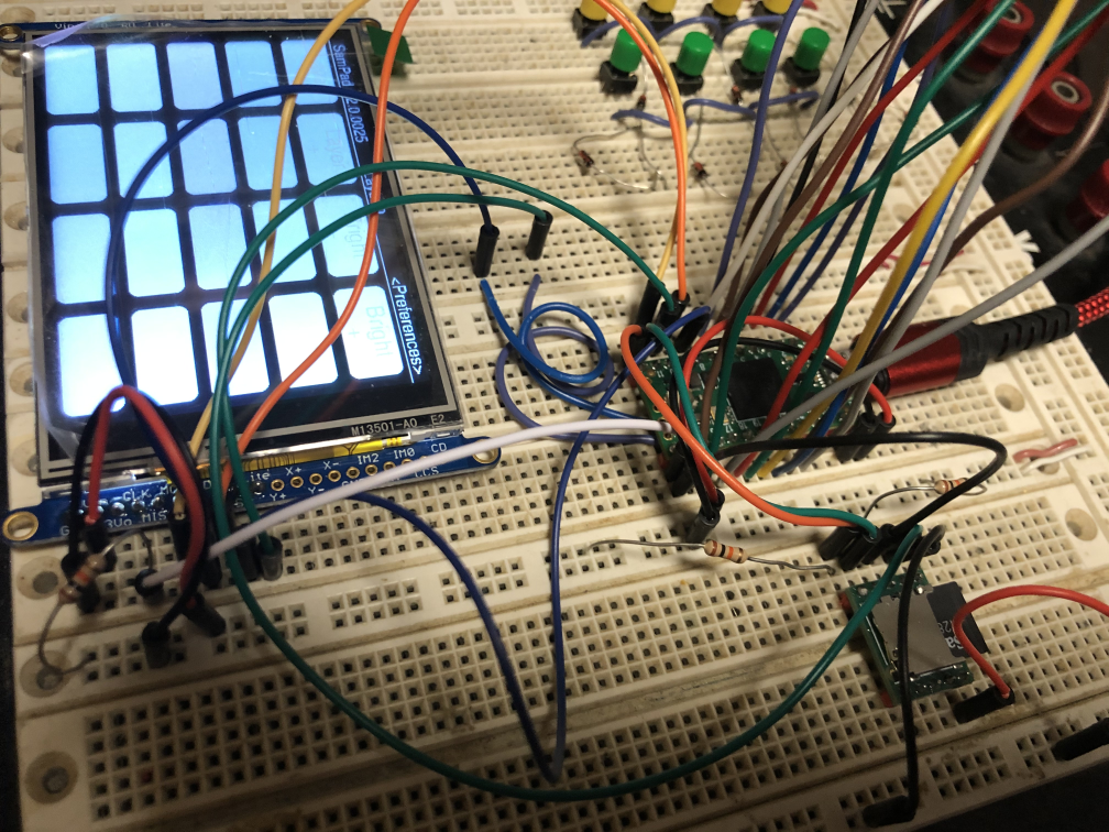
Phase 1 was to learn the KFLOP hardware itself. I breadboarded the KFlop to my Gecko G540 to make it easier to figure out the IO lines of the board and make changes as I attempted to control my Gecko G540. I then built an enclosure for the KFlop. Done.

Phase 2 was to attempt motor control with the KMotionCNC software of my Gecko and Mill, despite the fact that I didn’t intend to use KMotionCNC.

Phase 3 was to dive into the code for the new application. Here’s where the fun begins. My end goals were

  • A multiple window, modern user interface that was configurable and persistent.
  • A robust preferences system.
  • Extensive error trapping/correction including intelligent saving of parameters in case of a crash for easy restart..
  • A DRO module that allowed for ā€œundo-ableā€ changes.
  • A Jog/Manual module for the mouse, including keyboard and potential external hardware devices.
  • The ability to load, save, edit and run GCode files.
  • A CustomTool module for easily adding vb.net code and custom milling. This would be my “plug-in” system for what some call “conversational G-Code programming”.
  • Preparation for Backplotting options later by using existing code from my SubSpace 3D digitizing application.

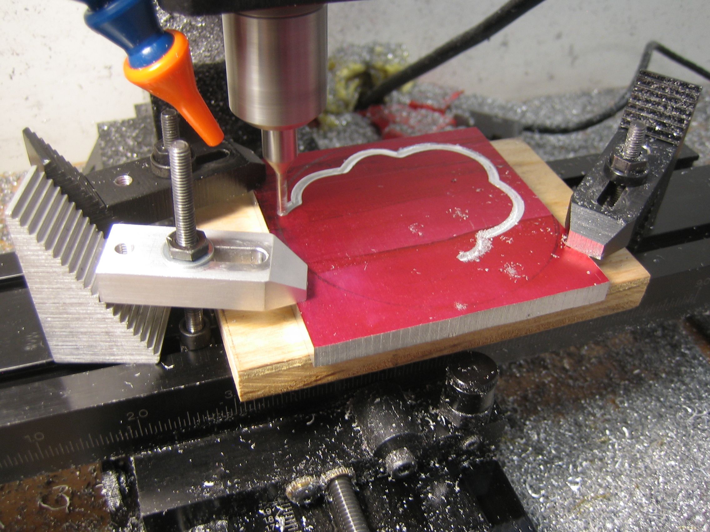
Thanks to Tom’s support at Dynomotion, answers to my questions were never more than a day away. It took about a couple months of spare time to write the code and get it all running. When this was originally written in August of 2014 I had milled several pieces successfully and only broken one end mill because of a bug! But, hey, at least I can fix my bugs! (Note, it is now 6 years later and Dynomotion’s support continues to be great).

I approached the writing of the application by breaking it into the modules I knew I would need. I began with what I call my Skeleton Framework code. This is a UI/Application codebase that I wrote years ago when DotNet first appeared that serves as the foundation for all my applications over the last 15 years. This foundation gives me a non-modal UI with all the library code I’ve written over the years including:

  • Advanced Generic Collections
  • Application and User Interface persistence
  • Common string parsing and handling
  • Process and Threading management classes
  • Form handling
  • History and Undo management classes
  • Hot Key management
  • My MScript scripting language for startup parameters

Using my existing Skeleton Framework as a starting point lets me skip all the mundane code and jump directly into the fun stuff. It provides the foundation for most of the applications I write for work and home.

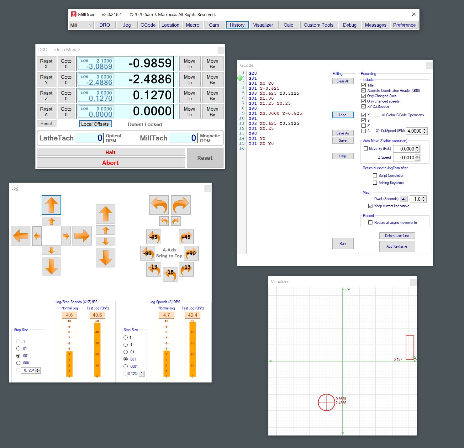
Update: Originally titled MillDroid because it was specifically for my Mill, I’ve since added a Sherline Lathe and converted it to CNC. Now the software can control both my Mill and my Lathe, switching between them with a button press. I have updated all the images in this blog entry to reflect updates I’ve made to the application over the last few years.

I started the application design by blocking out the User Interface into the following modules and began building them:

Note that I have updated these UI images as I have improved the application over the years.

First, the Tool Form, from which all other windows are launched. This is the center point or hub for the entire UI.

After the Tool Form, every form can be made visible or not and positioned anywhere on the screen and persisted. This makes your UI as configurable as you monitor size allows. I use a 30″ monitor in my shop and like to have everything visible on screen.

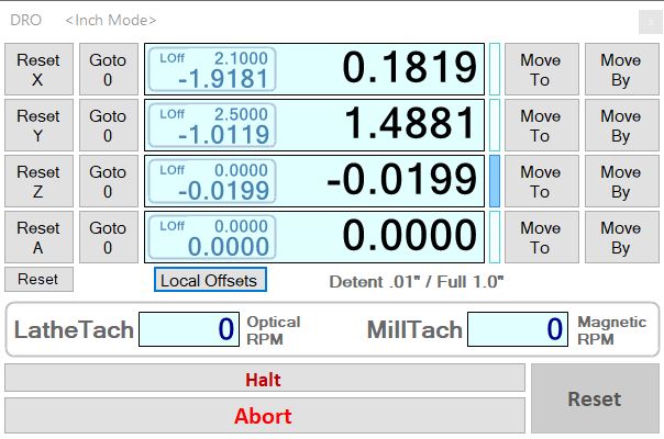
The DRO Form to display location data and allow changes to the data. It also provides functions for quick navigation and movement on the Mill and Lathe. Both my mill and lathe now have magnetic tachometers that provide pulses for the system. The Lathe also has an optical encoder that I built for spindle speed and threading functions that require tying it to the other motors. It also shows local offsets (if any), translations of machine space and information on my Pendant Hardware for full manual operation of the motors when needed.

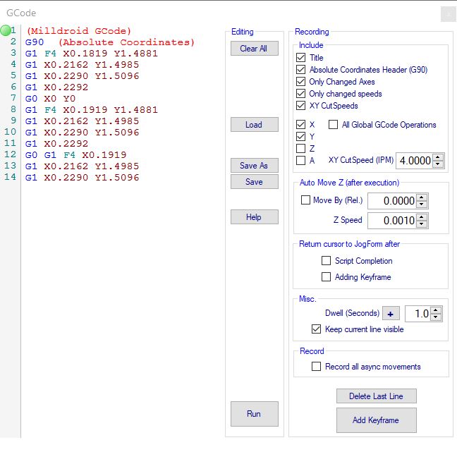
Next came the GCode Form for editing and running already prepared GCode. This allows me to edit GCode manually and contains a recording mechanism for auto-creation of GCode. I can jog the mill or lathe around manually or with the pendant and add key frames at any time, recording everything or only changes in certain axes depending on my needs. A nice addition that allows a building GCode for future use from operations done manually.

Ā 

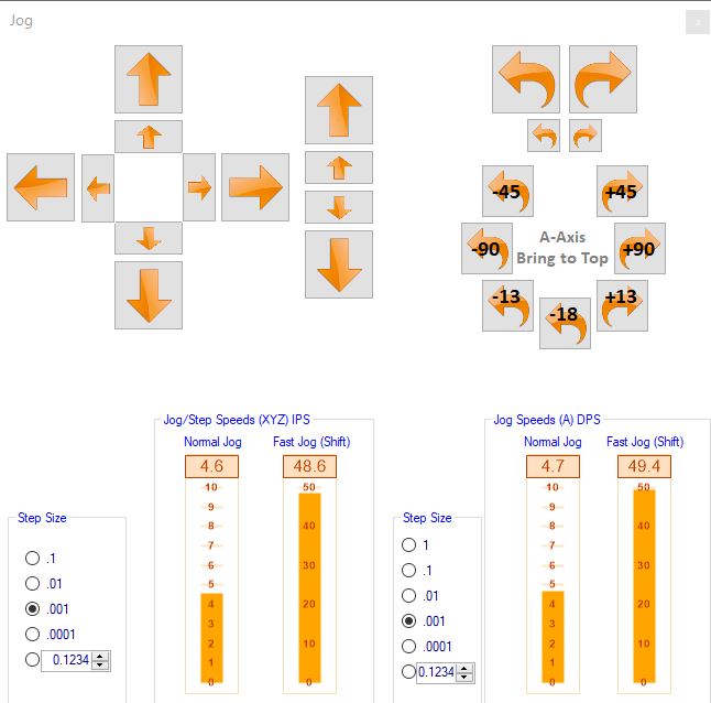
The Jog Form, for mouse and button manual control of the mill and lathe. All the buttons in this form can be accessed by hot-keys such as the cursor buttons, or an external device on a USB port. I used a Griffin Knob USB wheel for a while but they stopped supporting newer OSes and it was a bit laggy. That led to the development of my pendant box (see MillDroid Pendant elsewhere on this blog for details). I added a few macros for my rotary table control for functions I find myself using often. All jog or step speeds can be changed as well.

Ā 

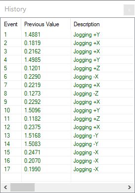
Between the DRO and Jog Forms there are plenty of ways to move the axes manually, but what about when I make a mistake? Ever move an axes then realize that you shouldn’t have? Now you have to figure out how far you’ve moved off course That’s what this History Form is about–it records every change you make anywhere in the application and displays it for you. A true Undo would be far too dangerous on a motion control device, so this lets you see what you did, then copy and paste the old value where you might need it in the DRO. Much more flexible than straightforward Undo/Redo functions.

Ā 

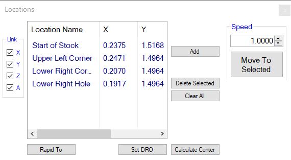
The Locations Form to allow quick movement and recall of positions on the mill and lathe. I can record current positions of the mill for any or all axes, then move between any of those stored positions quickly at rapid or cutting speeds. Notes can be added to each location to help when human memory fails. Think of this as ‘bookmarks’ on the mill & lathe that can also be used for straightforward cutting operations.

Ā 

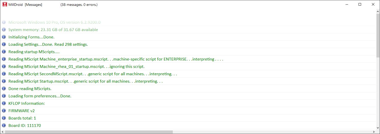
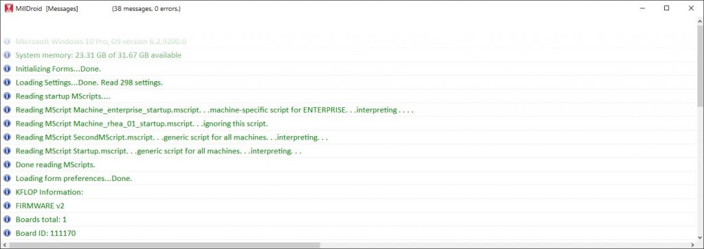
The Message Form provides feedback from the application. This is where general message, warning or errors are presented so they can be logged, without bringing up an application-halting dialog box. It’s proven handy for later review of debugging issues also.

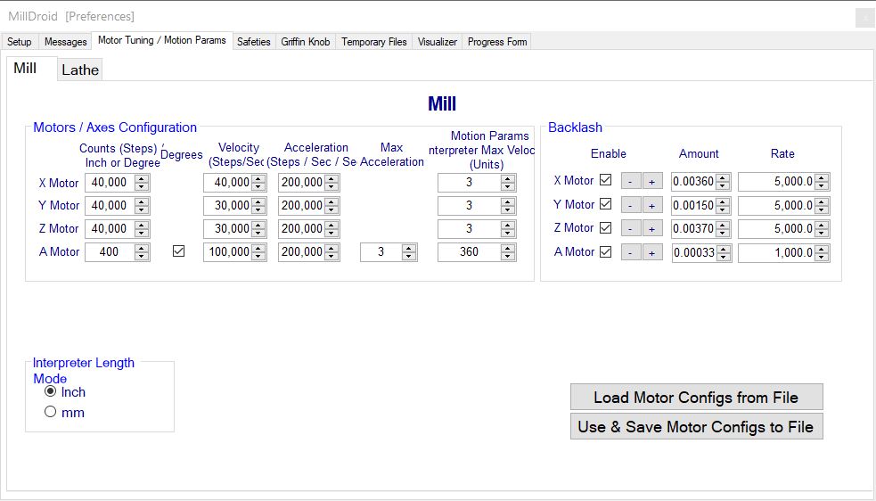
The Preferences Form for the default settings on the application. Every setting in the application can be changed here. The most complex is the Motor Tuning/Motion Params tab. Since multiple preferences can be save/loaded, I have some very fast motion settings for testing and everyday settings I use with safer motor speeds that are more appropriate for a mill/lathe of my sizes. It’s nice to be able to switch quickly between them.
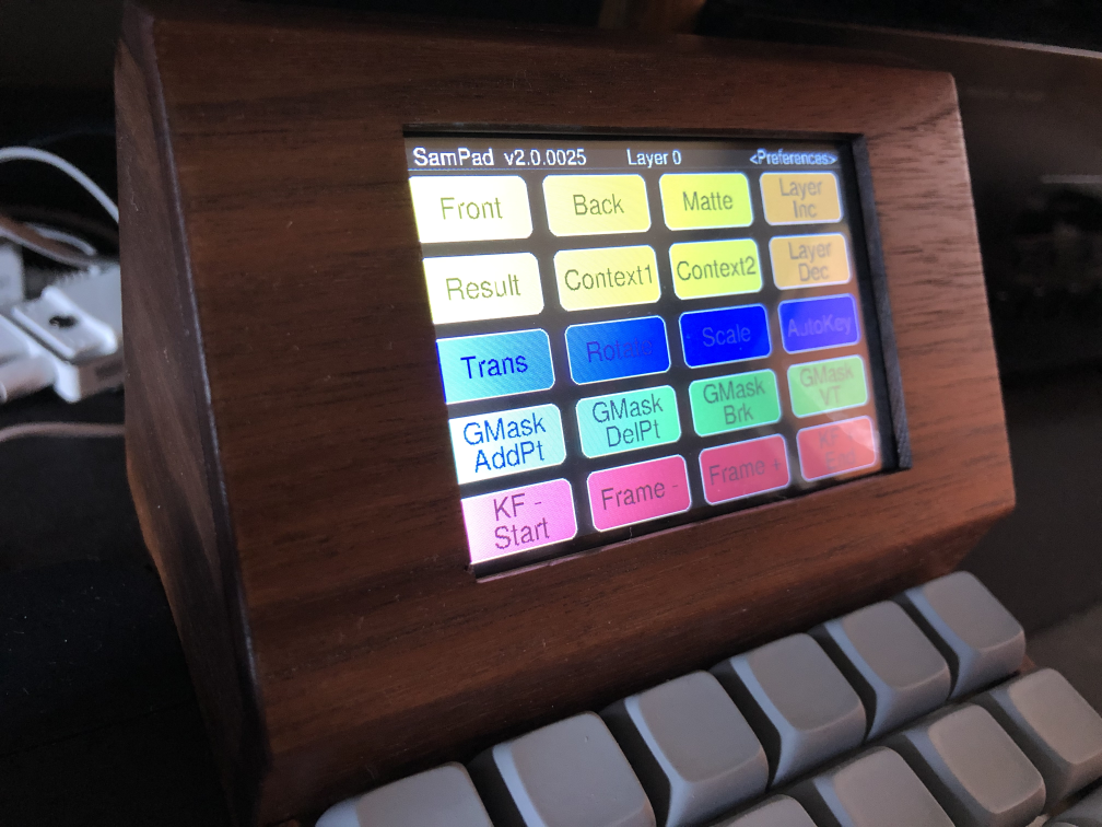
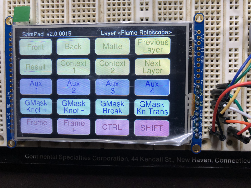
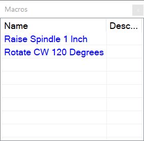
Ā 

Ā 

This is the Macro Form.Ā  A folder is parsed at startup and a macro “button” is shown for each script. This allows quick additions of little GCode Snippets that can be accessed quickly.

Ā 

This is the Visualizer Form. It provides a simple view of the mill or lathe cutting tool and stock locations. It isn’t very elaborate, but it helps when debugging or working on my code when I’m not actually connected to the mill.

A simple Debugging Form lets me see which threads on the KFlop hardware are running C-Code.

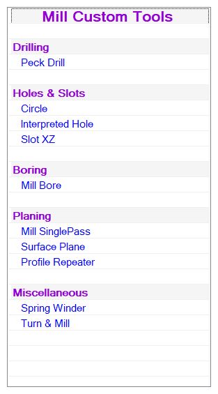
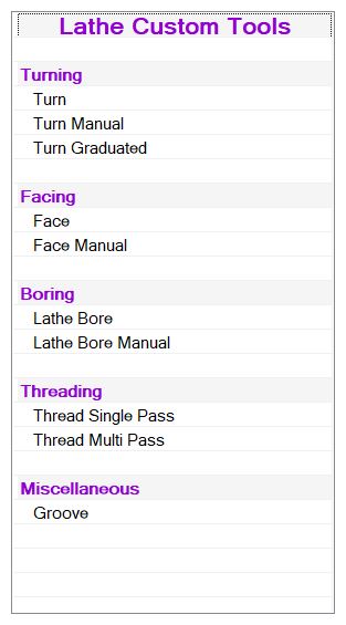
CustomTools are my “plugins”, or options for what “conversational gcode programming”. These plugins are modules with user interfaces that make it easy to perform complex operations for which you don’t want to write repetitive G-Code. They are grouped into Mill and Lathe Custom Tools.

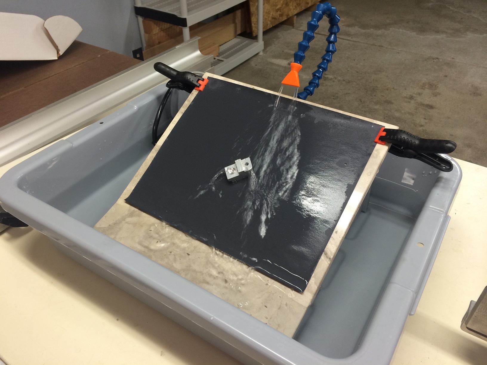
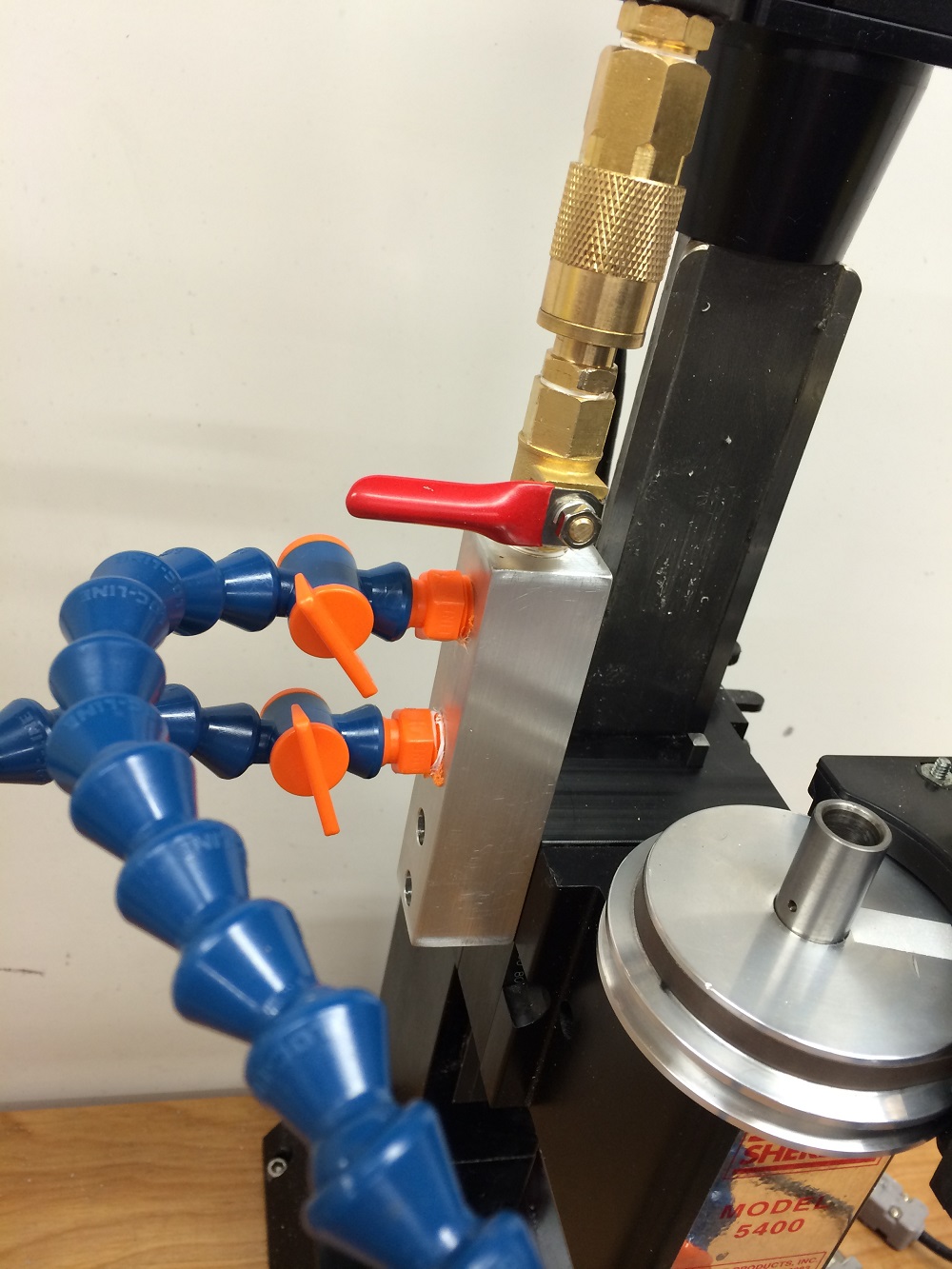
Programming-wise, there is a Base CustomTool Class, which is inherited by each of my custom tools. It takes only minutes now to write a new CustomTool and I have many. CustomTools give me the option of starting anywhere in their cycle in case I need to redo something. Each has an accompanying help file. They can also output their commands to a G-Code file log for later re-use. A Last Pass Alert plays a tone (and voice) and shows a Dialog box awaiting a continue order before a finish pass is made (if desired). This lets me decide if I want to increase the spindle speed or decrease the table speed for the finish pass–very useful when flycutting or performing other finish cuts. Most support spring passes if useful. I often like to add a little cutting fluid and increase the spindle speed for a better finish on the last pass and this keeps me from “missing” the chance on a long-running operation. I can also chose to repeat the last pass as many times as I like. All CustomTool setting can be saved to files for later use.

You will notice that some of my CustomTools, such a PeckDrill, perform operations that can also be done with GCode. Sometimes I like to write my own custom tool for an operations just because I want to understand the process better; other times just because I wanted some added flexibility or control.

Ā 

All CustomTools have an accompanying ProgressForm. It allows modification of the functions all CustomTools have in common, along with starting/restarting and monitoring of passes, their elapsed time and prediction of completion. The Progress Form allows start or end on any pass, previewing the cuts, graphing the pass depths for debugging and listing of all the passes. Handy for preventing accidental crashes.

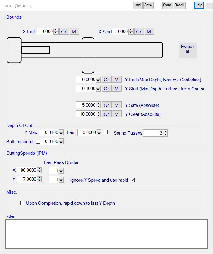
One of the more useful CustomTool plugins is Turn. Set the start and end, beginning of cut and depth of cut along with some other items and lathe turning/stock reduction become fast and easy. Most of the CustomTools support similiar options, including notes, what to do upon completion and the ability to load save settings and transfer them into a buffer for use in other CustomTools. Built it help is available as well for each tool.

Ā 

Ā 

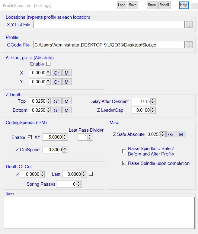
The ProfileRepeater CustomTool takes a G-Code file and repeats it over various depths. Lots of options to play with here including repeating the profile in multiple x and y locations for multiple parts builds.

Ā 

Ā 

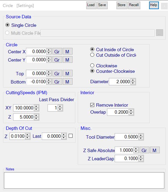
The Circle CustomTool cuts single or multiple interpolated holes (circles), removing the plug or all of the stock within the circle. Good for generating all types of circular holes. Again, plenty of options with which to play.

Ā 

I’ve recently added CustomTools for internal and external threads, part arrays and boring operations. Some days I spend more time writing interesting tools than making parts, but that’s what keeps it interesting! I’m now working on a g-code backplotter to visualize all the work before and while it happens.

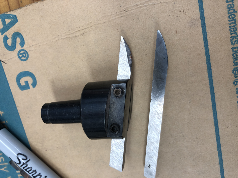
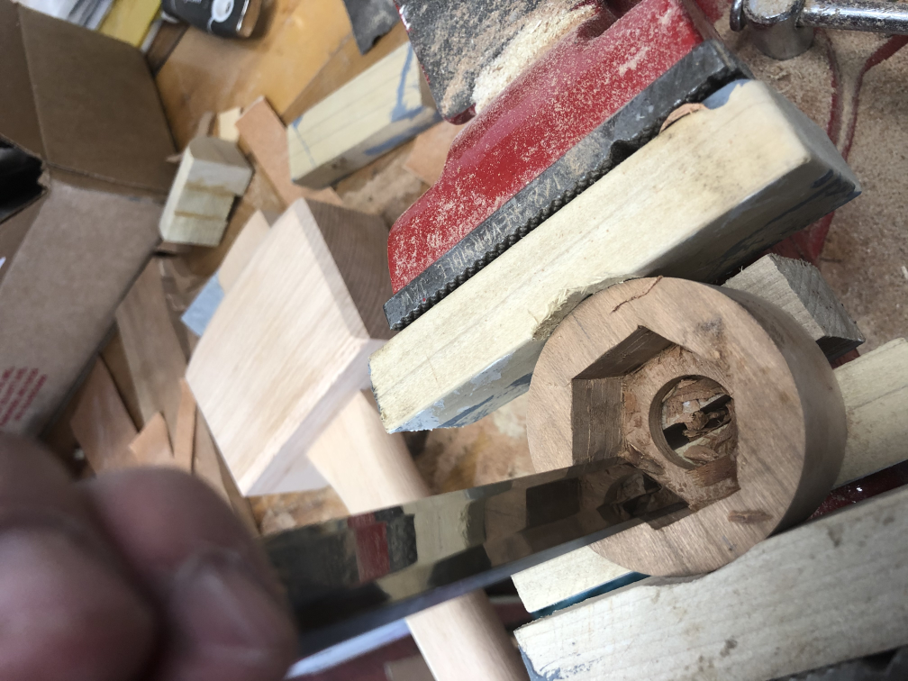
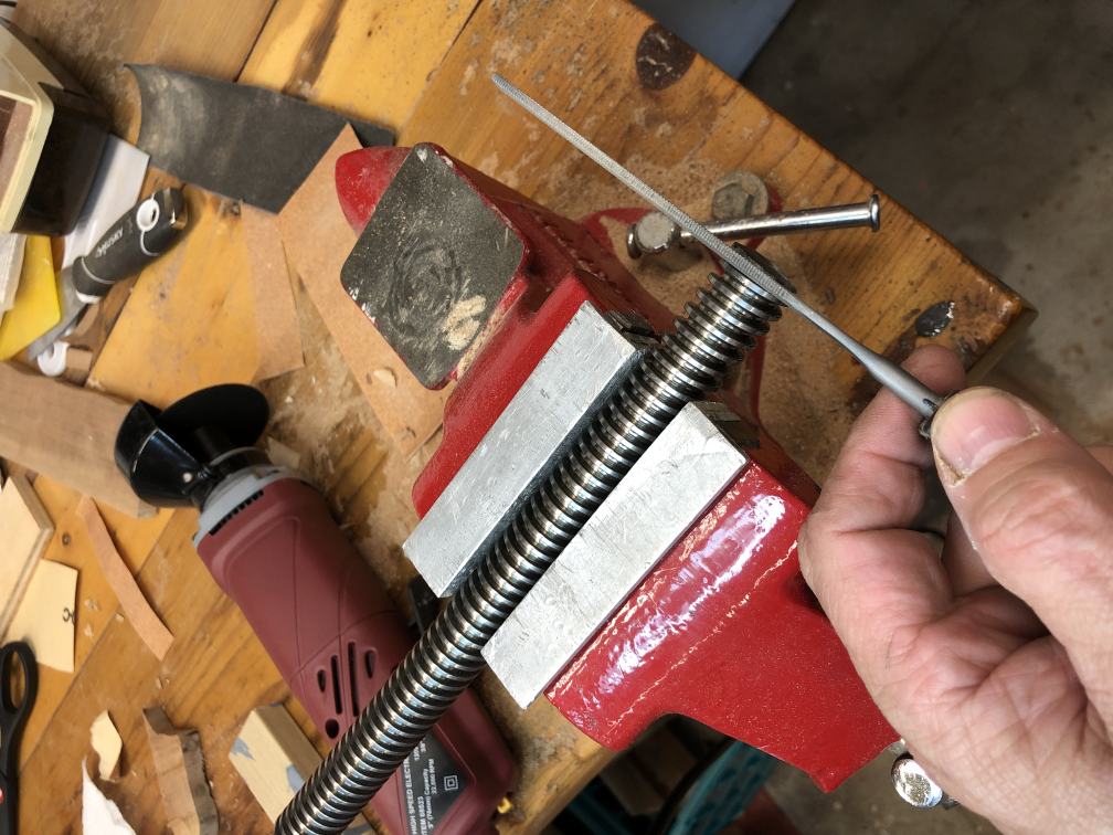
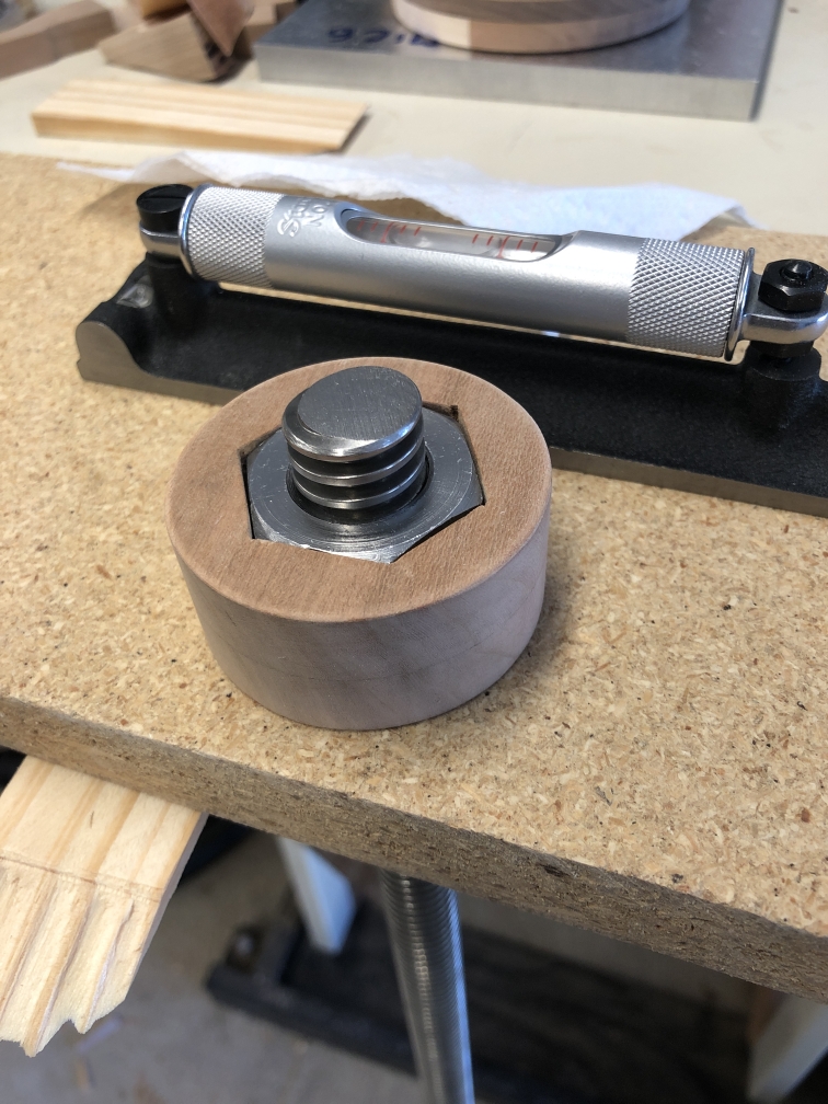
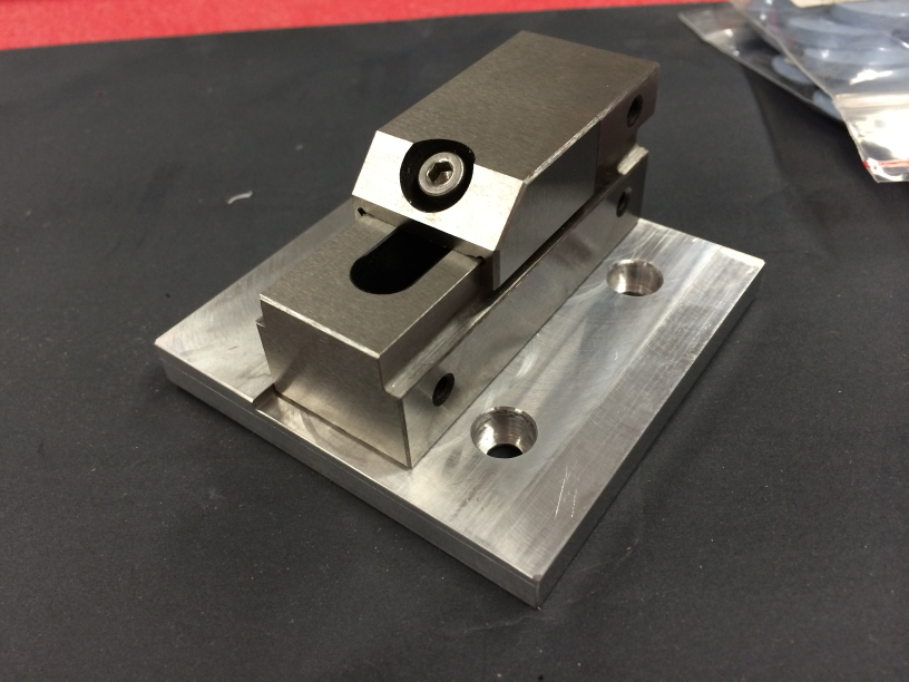
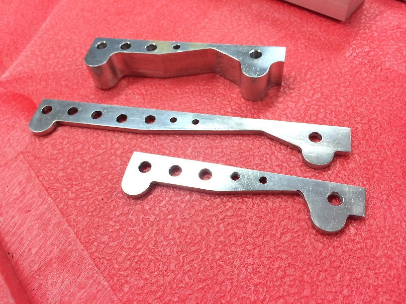
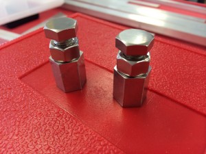
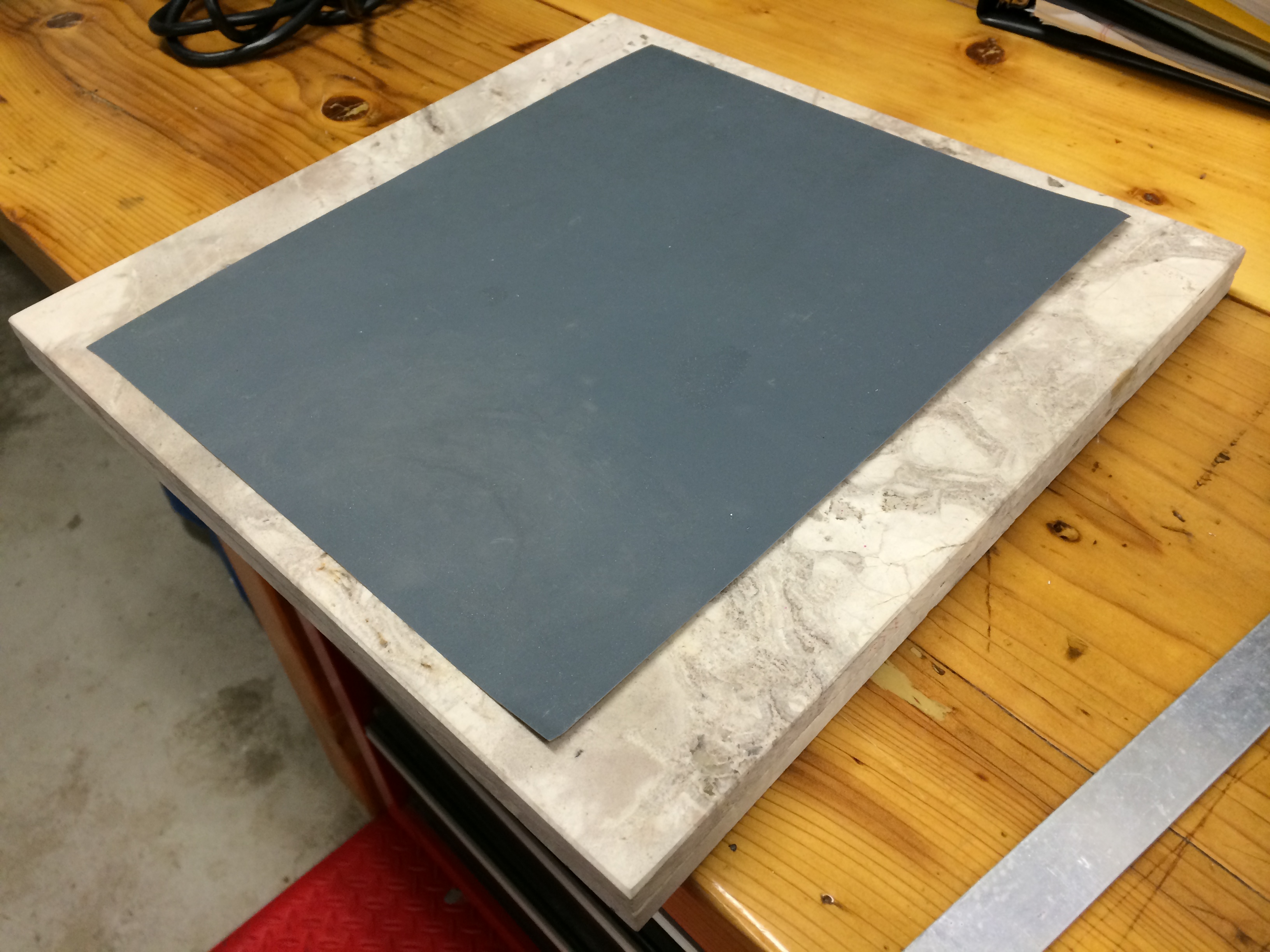
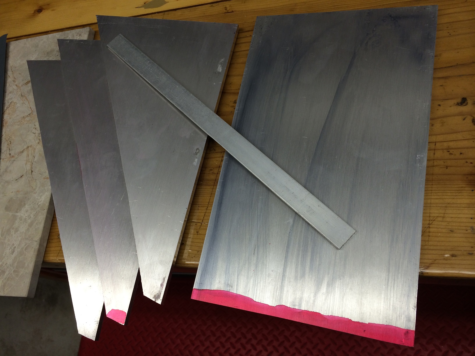
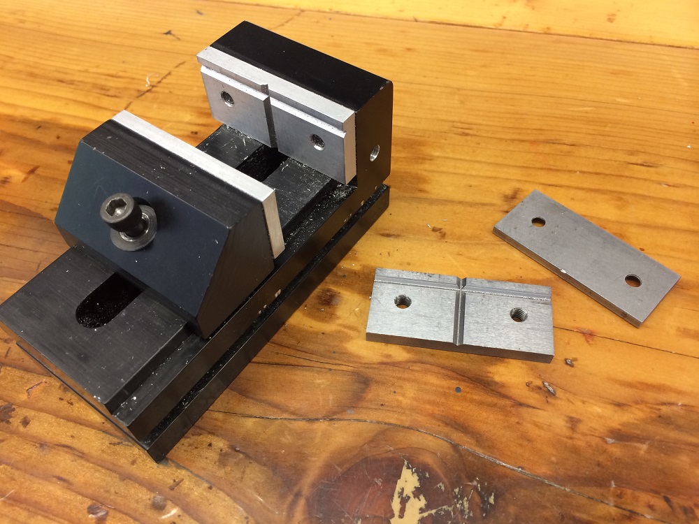
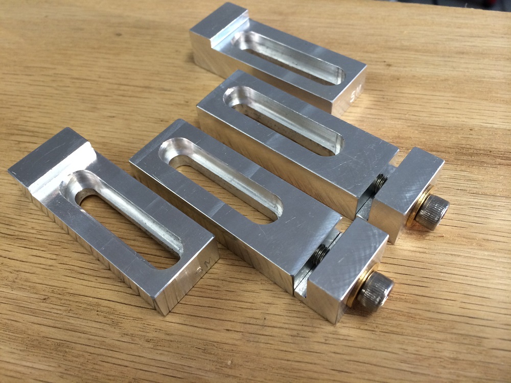
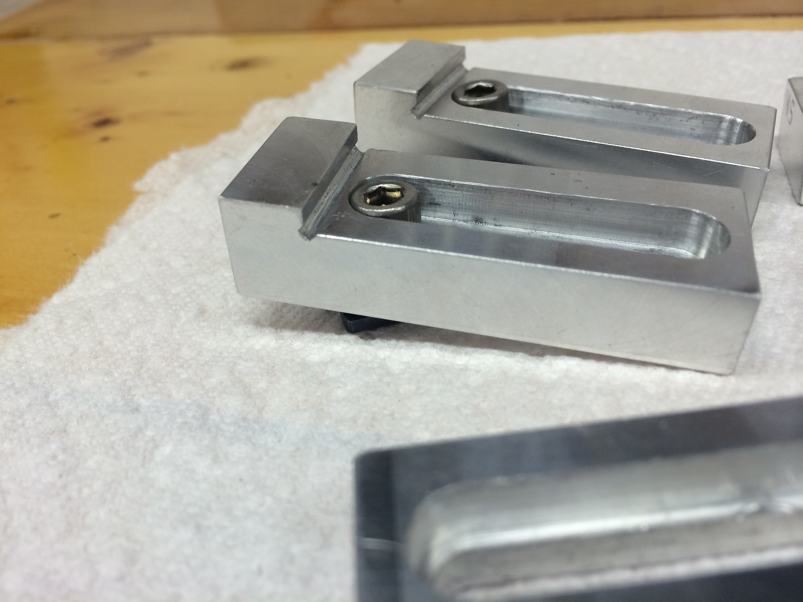
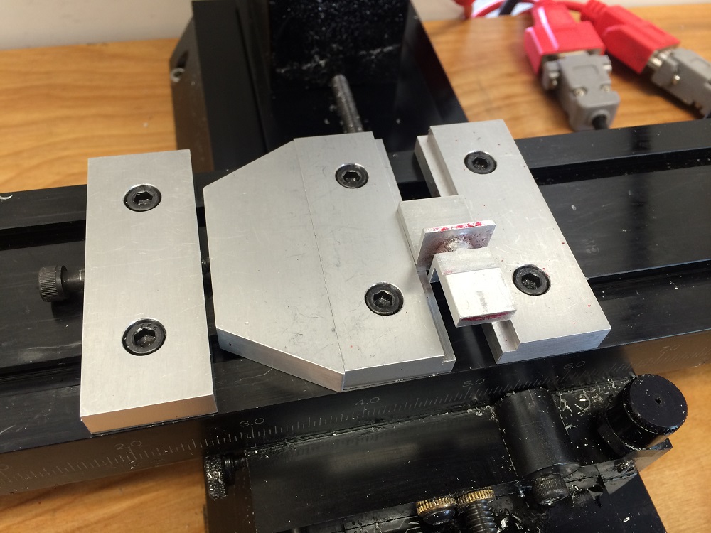
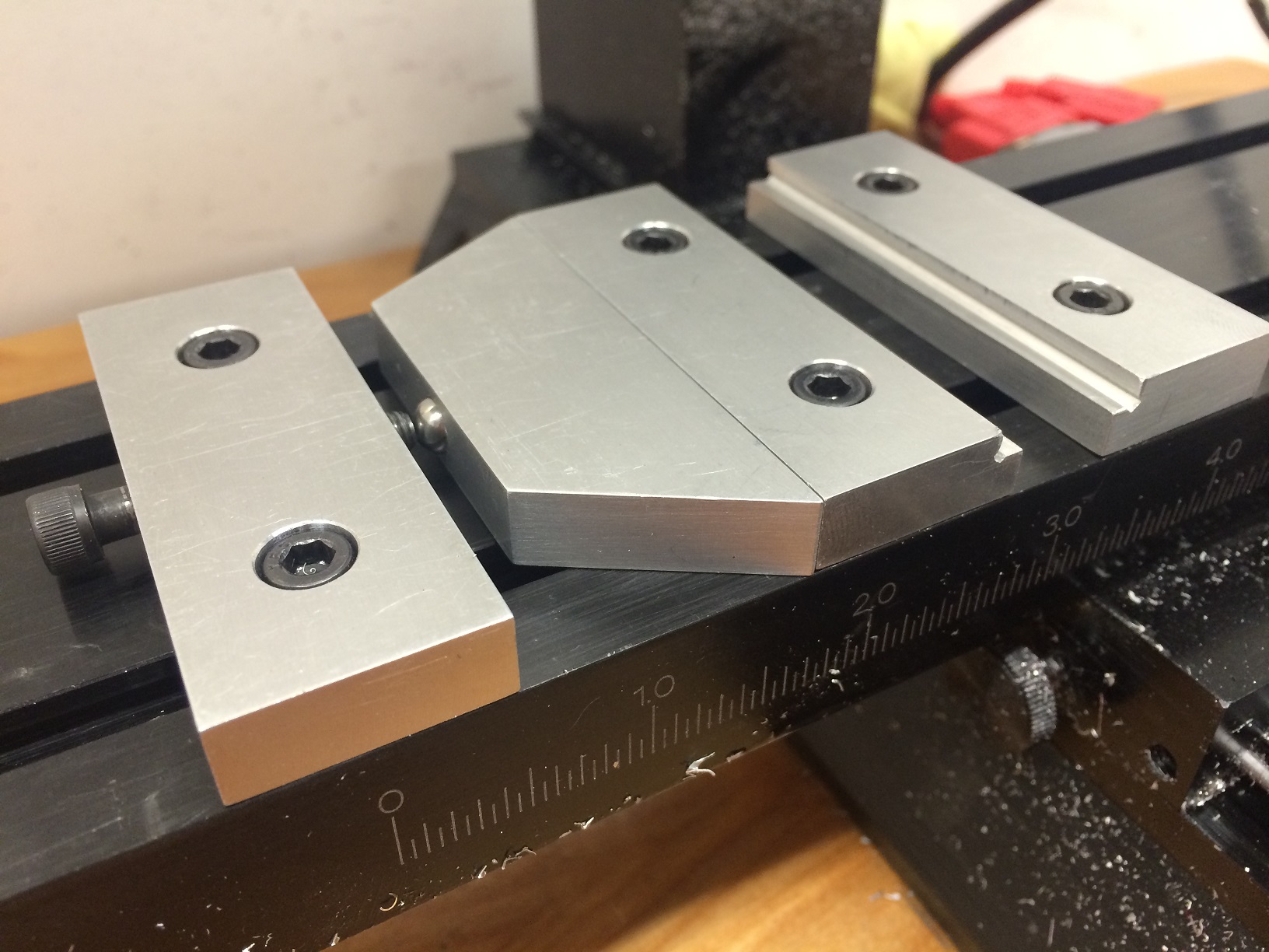
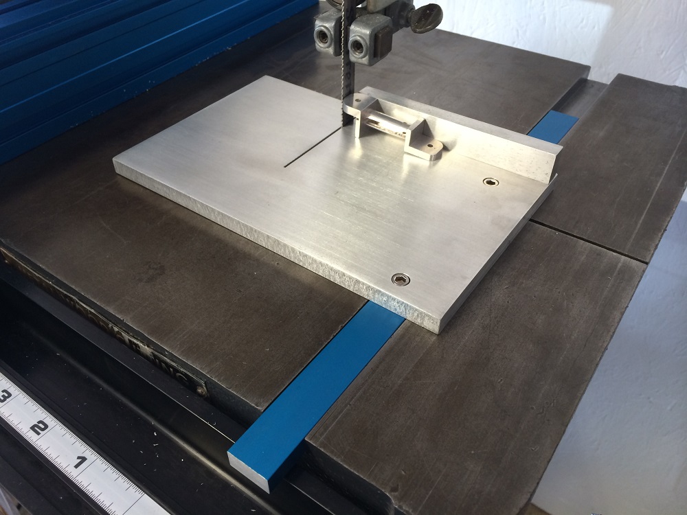
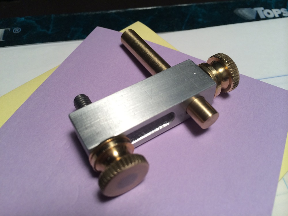
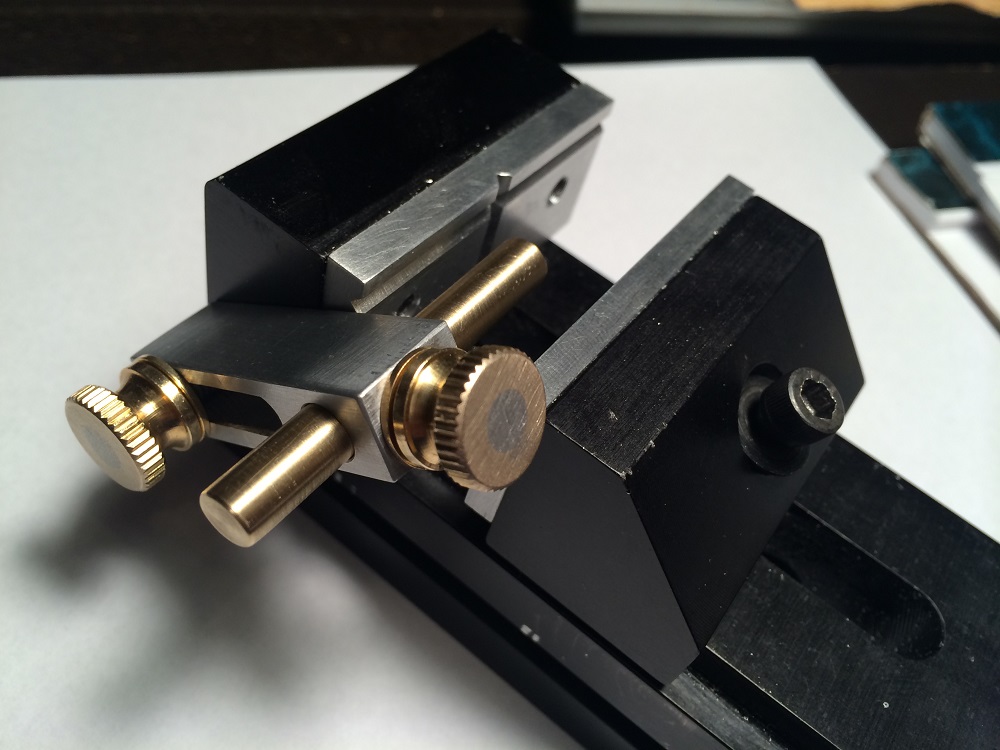
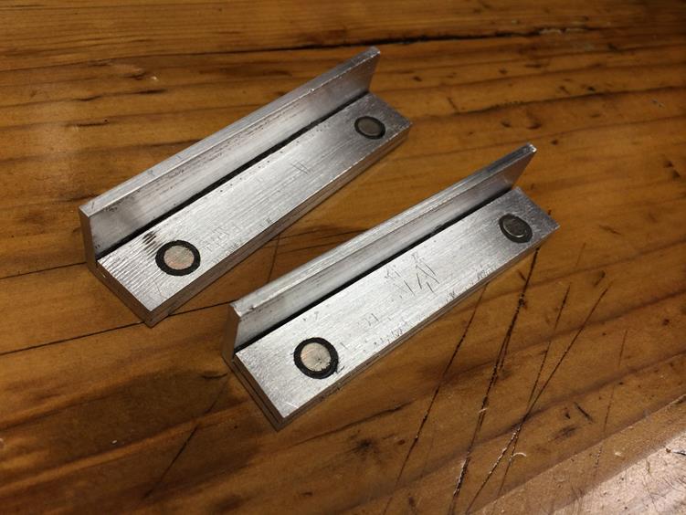
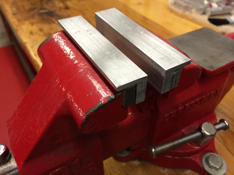
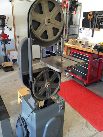
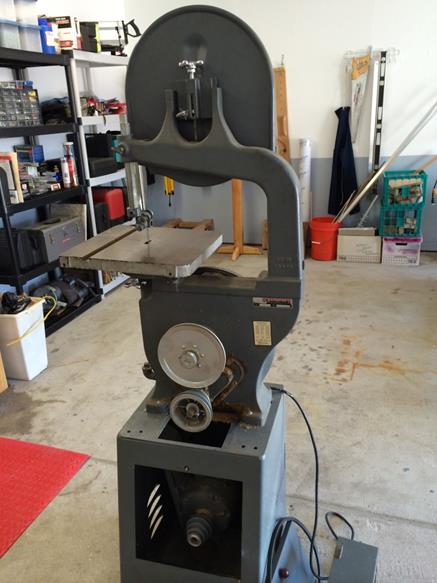
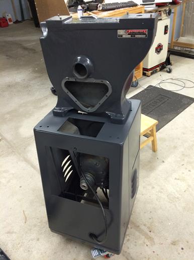
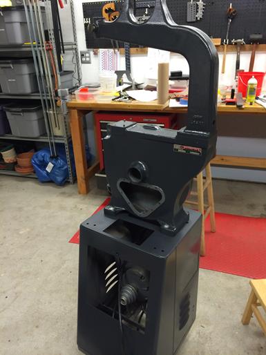
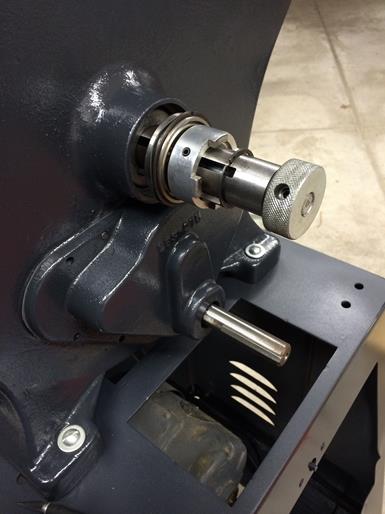
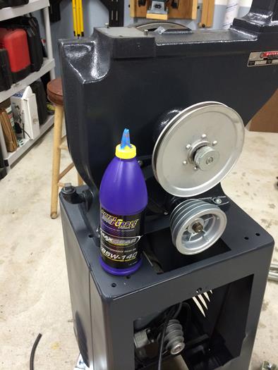
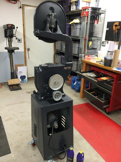
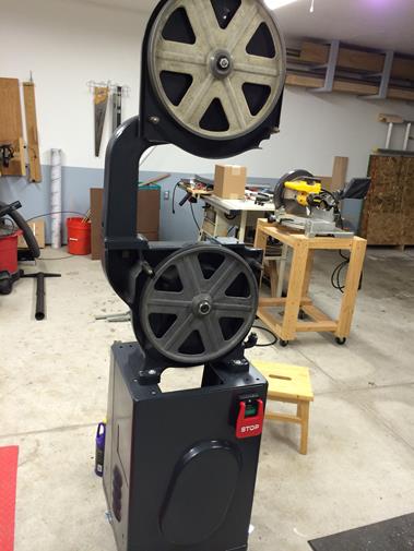
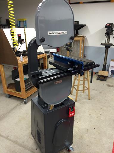
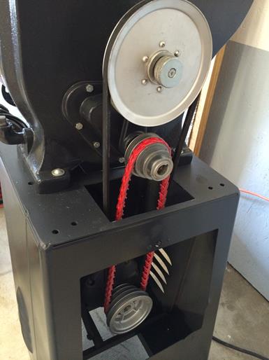
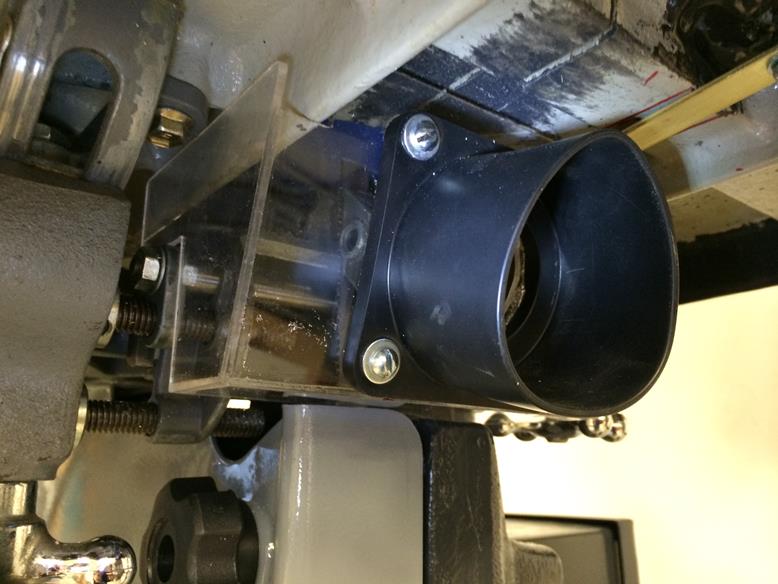
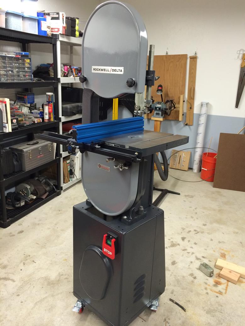
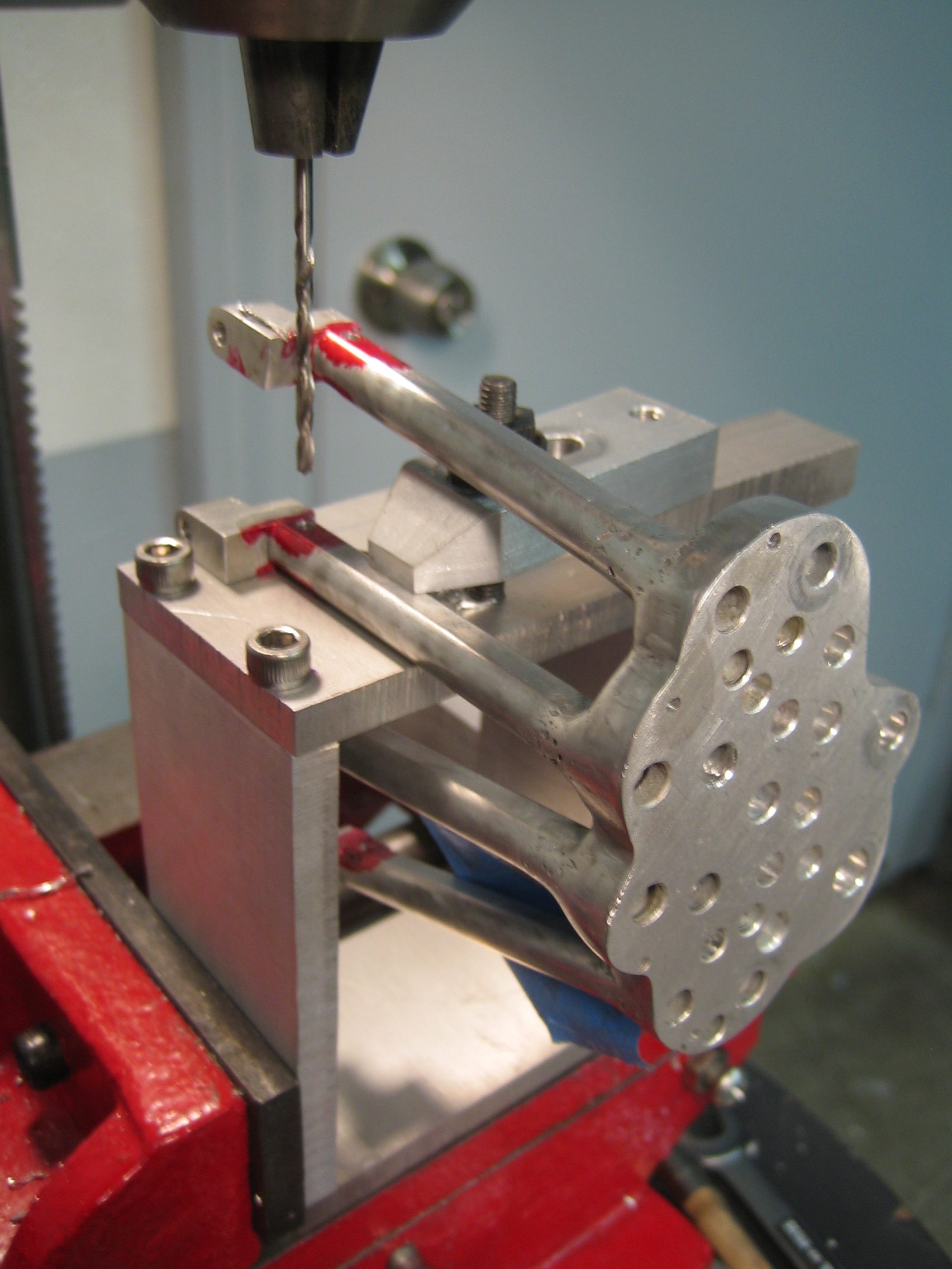
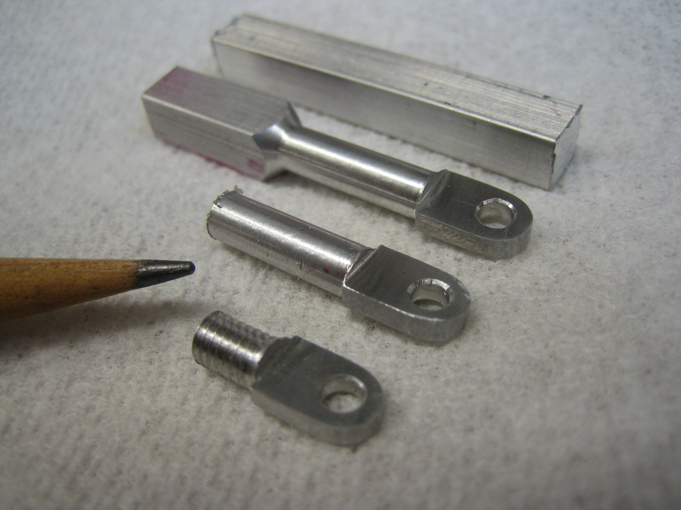
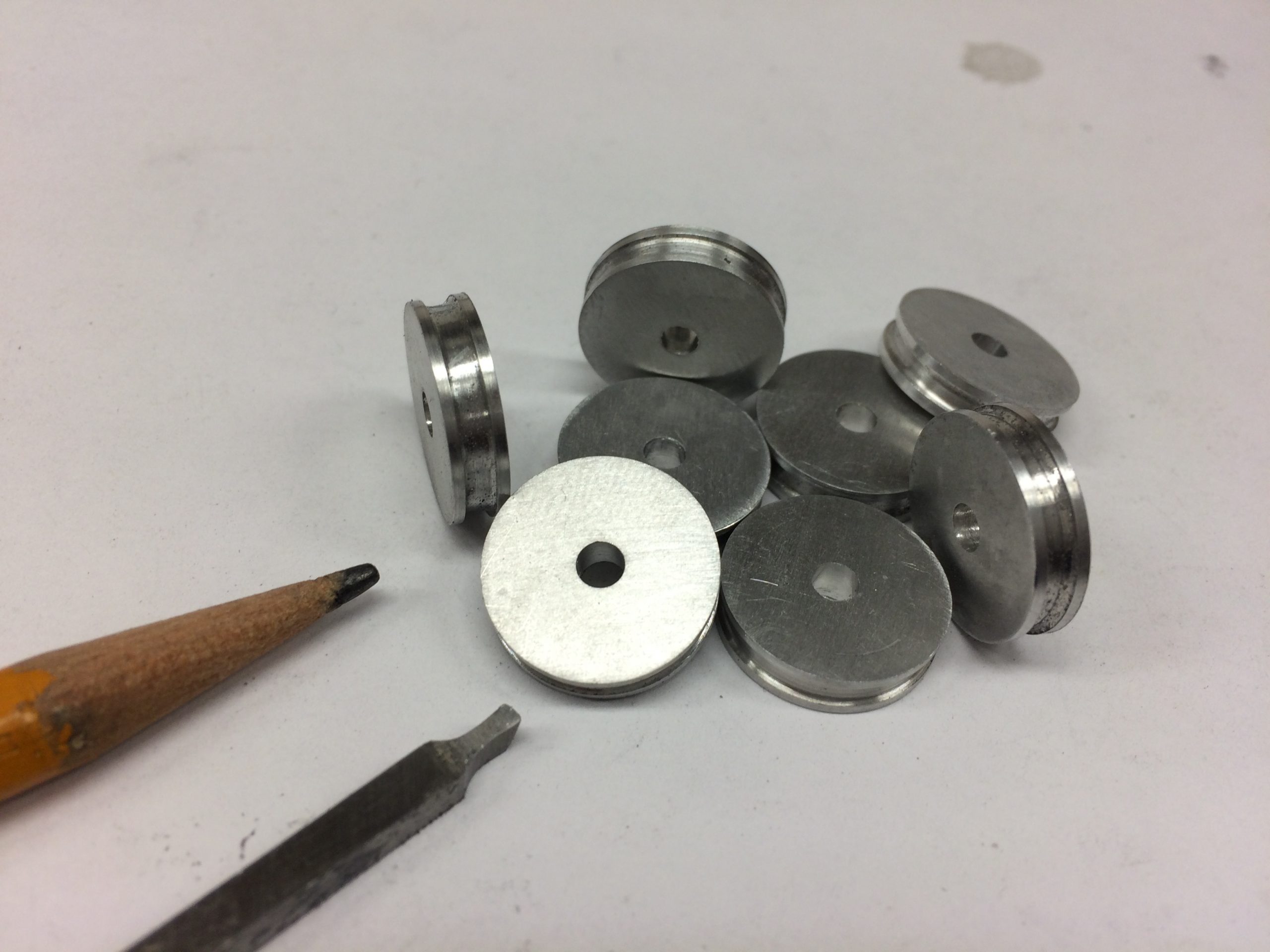
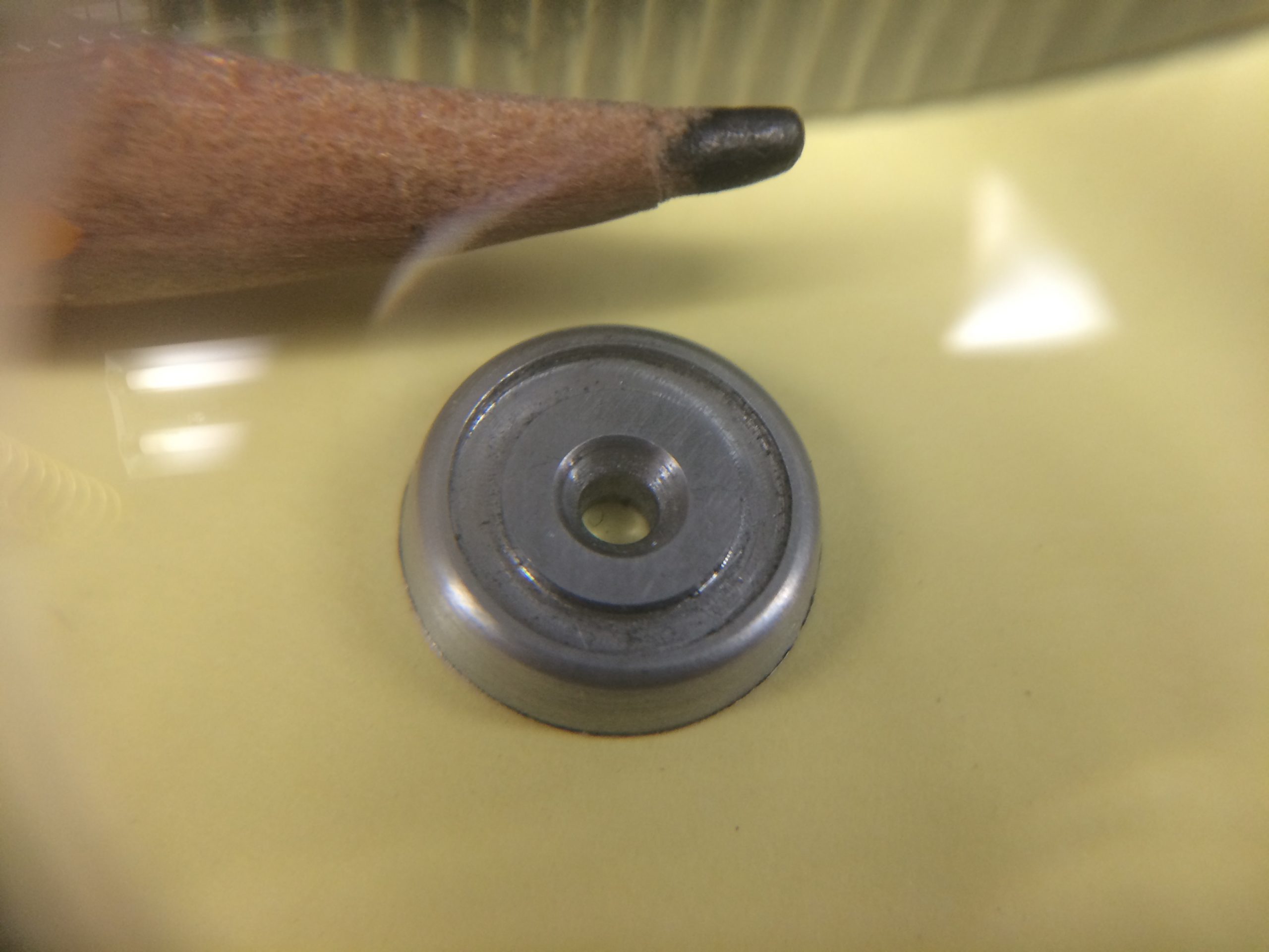
I used the alpha and beta phases of my MillDroid software to create a bunch of additional hardware tools for my mill and bandsaw. Like most of my code writing projects I’m continuously adding features and the apps become dynamic projects, evolving over time as my needs change. Now that the code has matured past the release phase, I can use it daily, confident in its stability.

I now have over 30 CustomTools written for the application.

Ā 

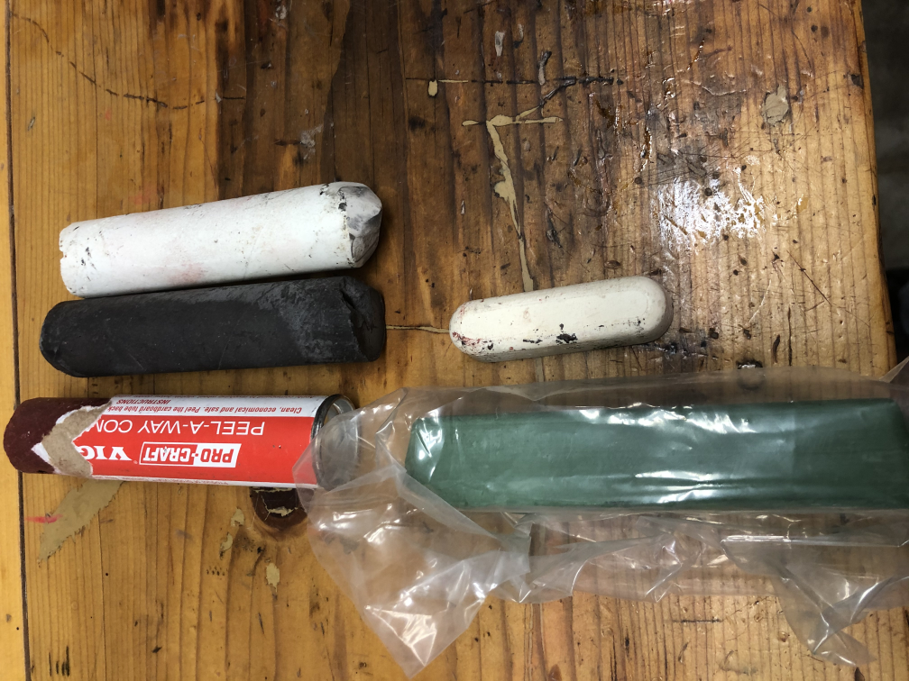
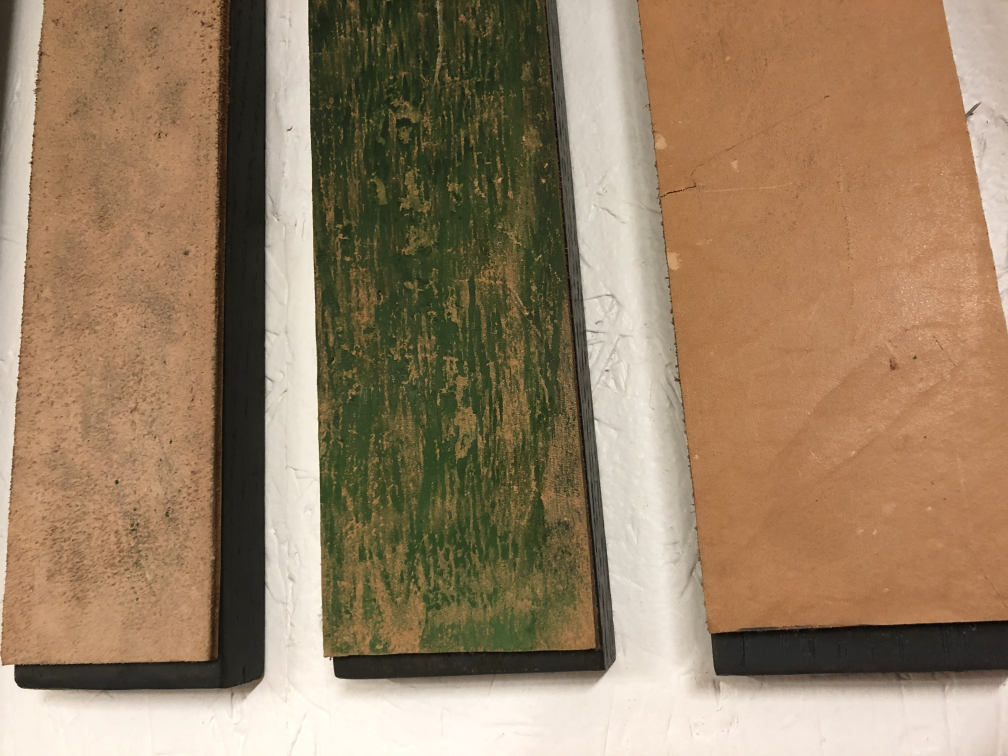
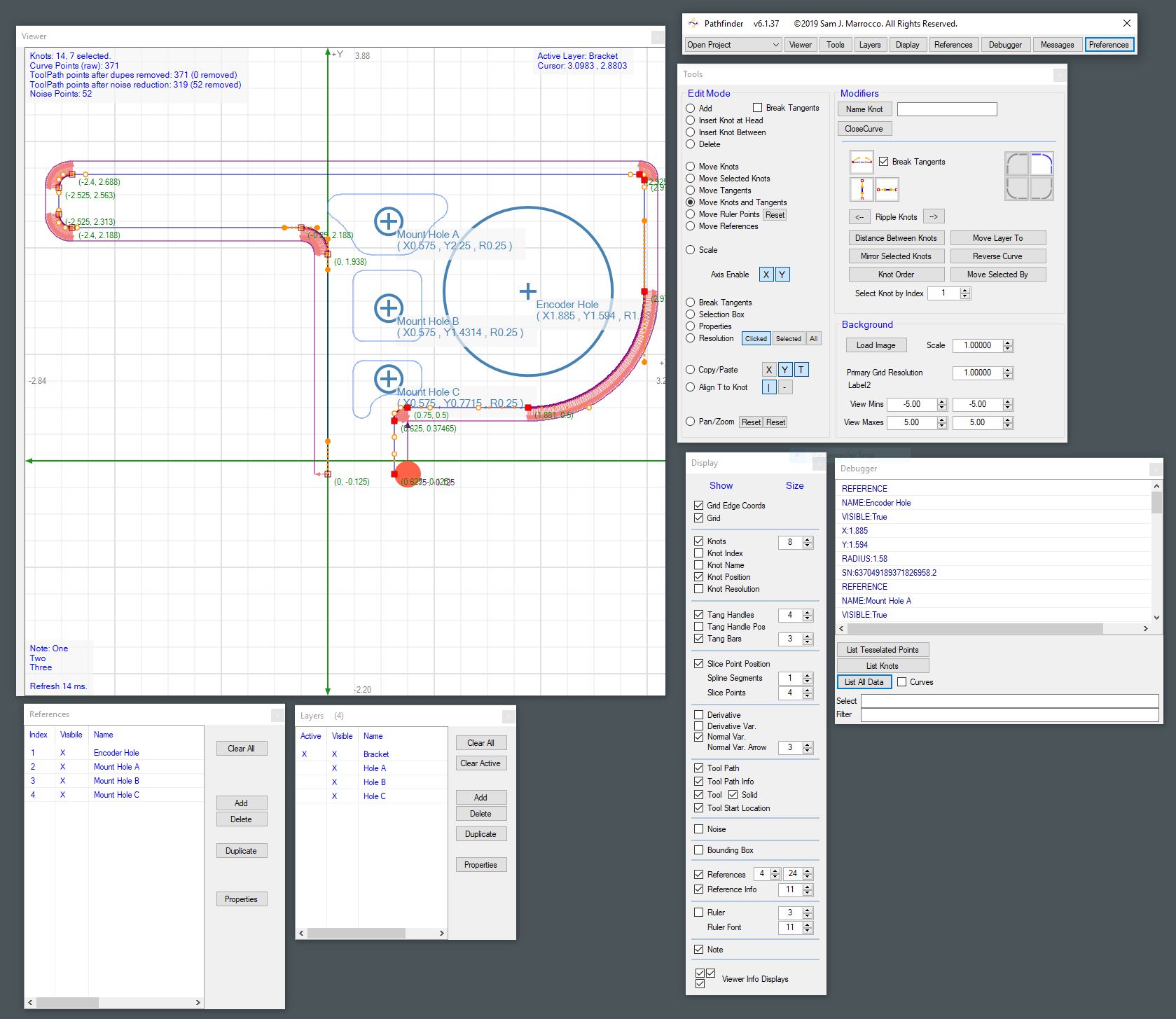
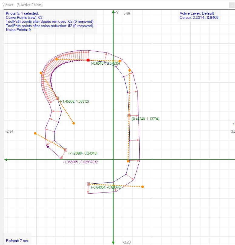
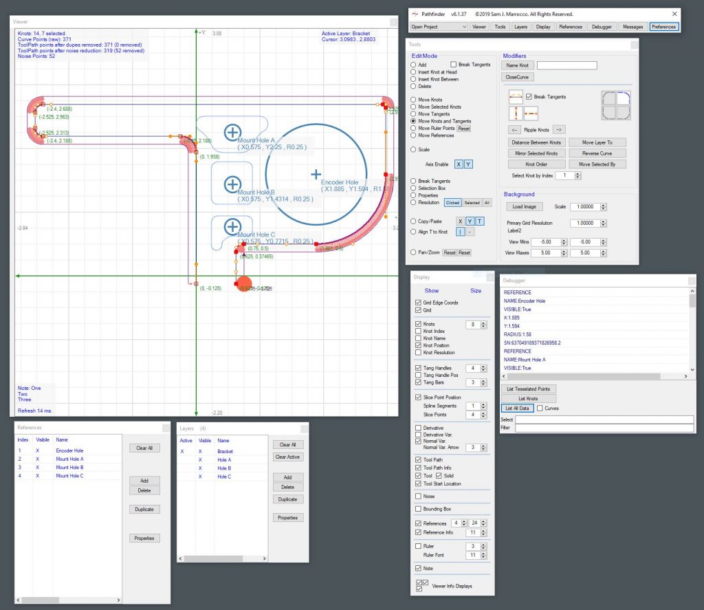
The Curves CustomTool started as a quick drawing tool for milling directly from a drawing or sketch. Like most of my projects it snowballed into a bezier curve-based drawing application that I now call Pathfinder. You can find it in the Projects section of this blog, but here’s a snapshot. I now use it to design parts using curves and output GCode directly to MillDroid.

PathfinderAllForms

Ā 

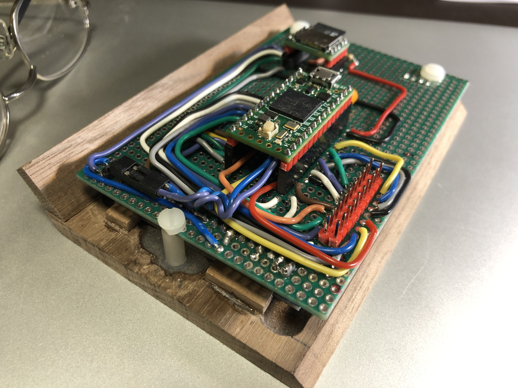
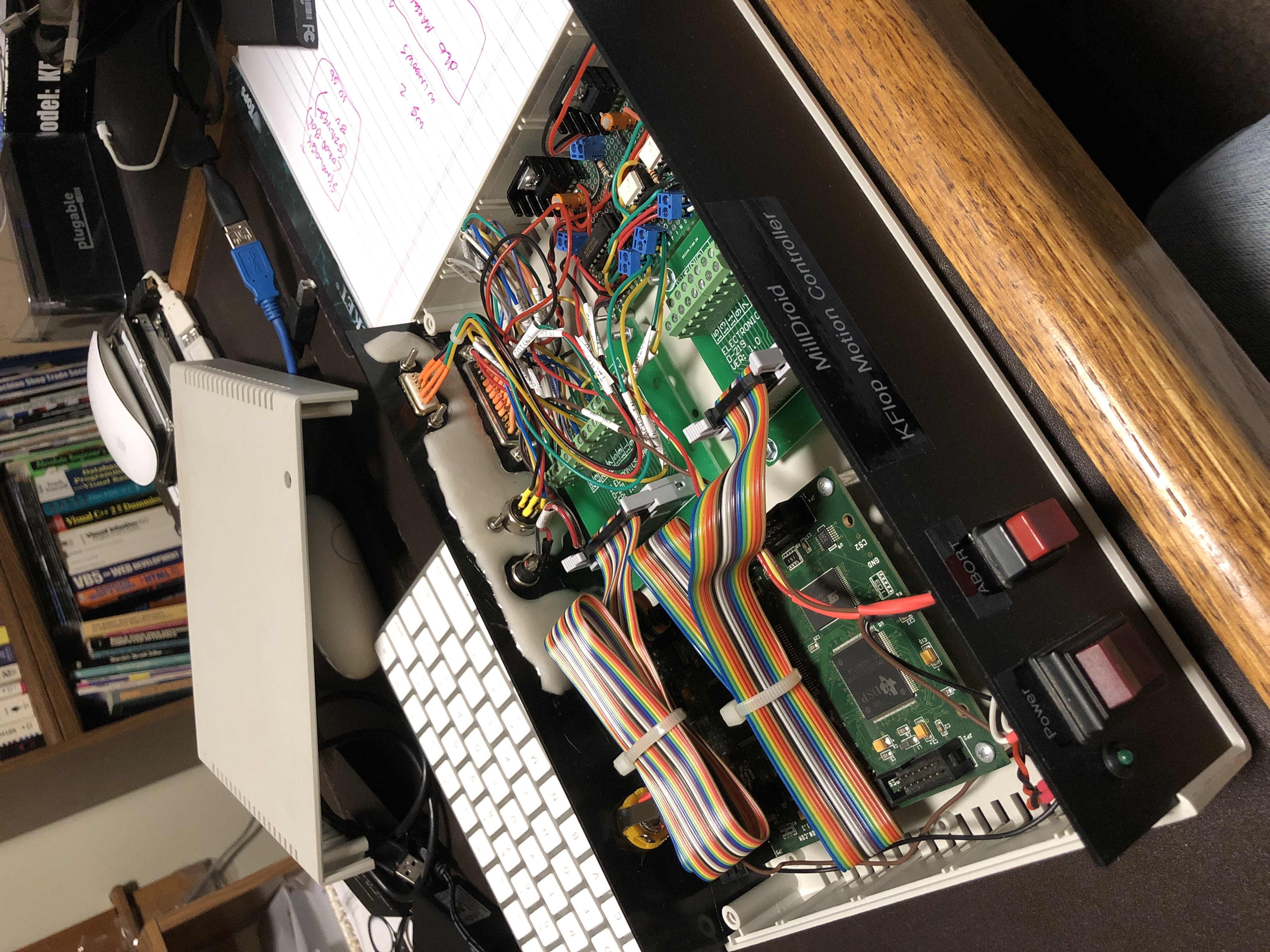
Here is a pic of the original KFlop-based Motion Controller I built for the application:

OEEK1323
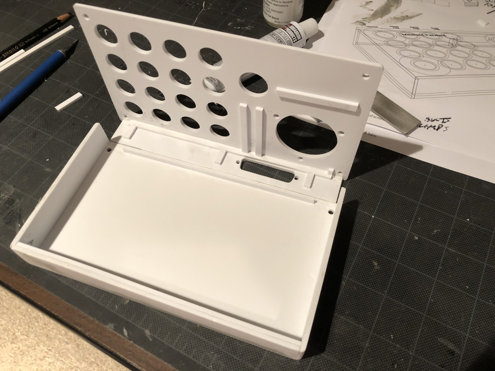
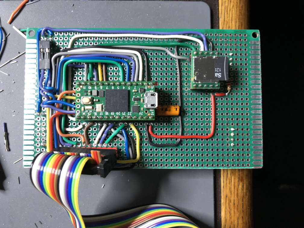
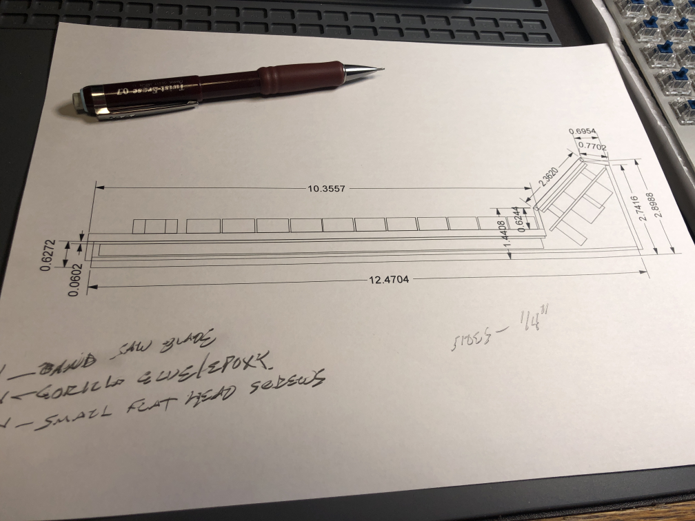
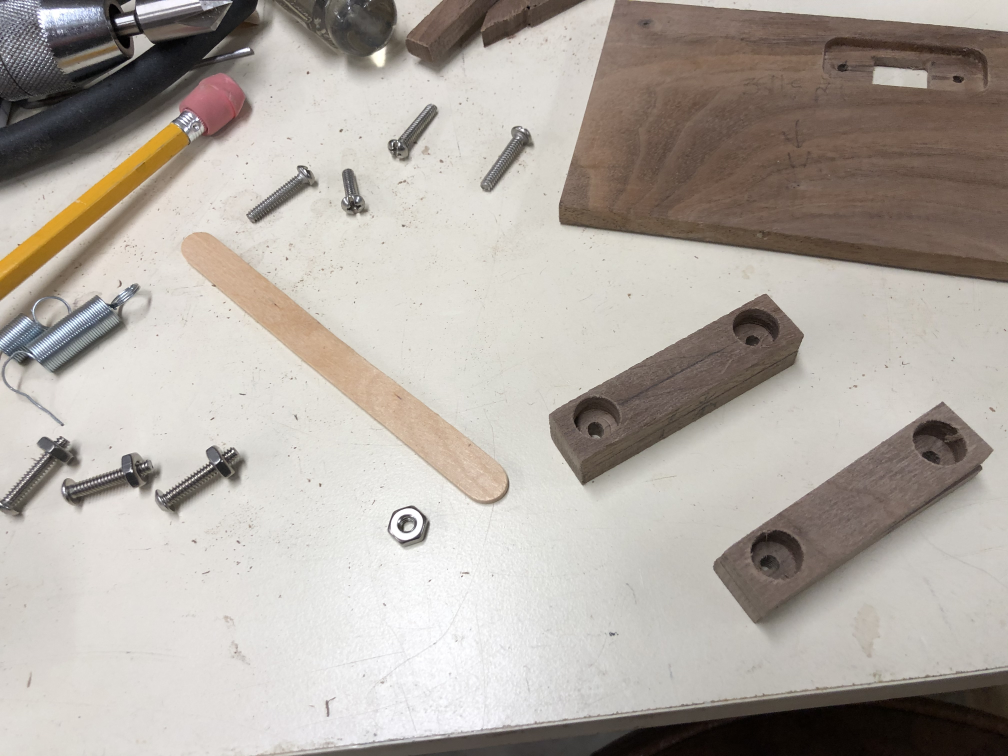
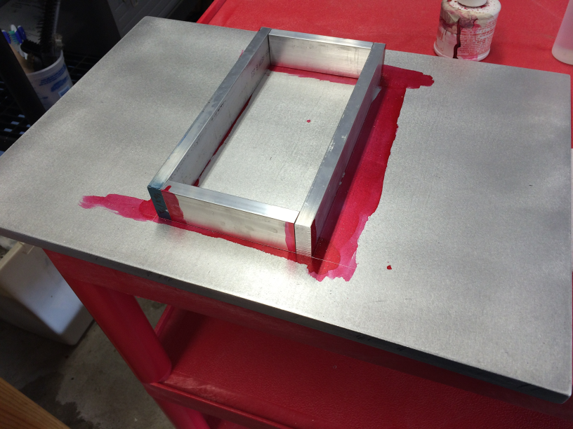
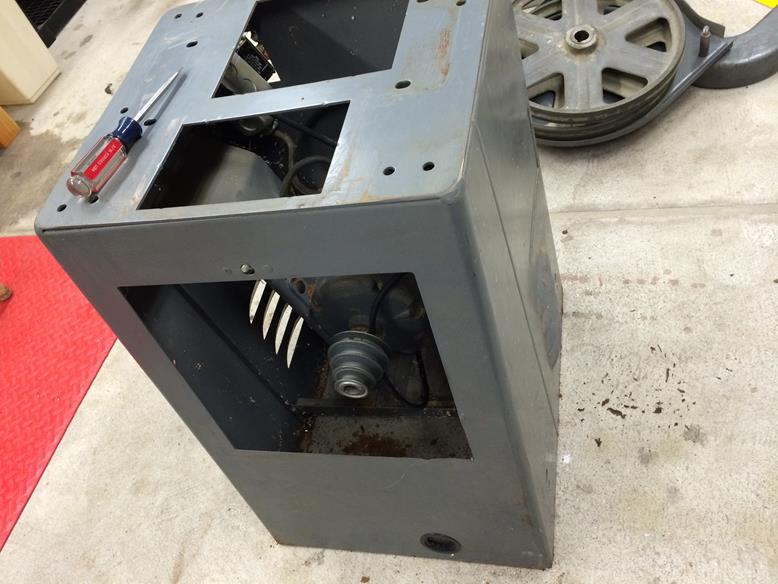
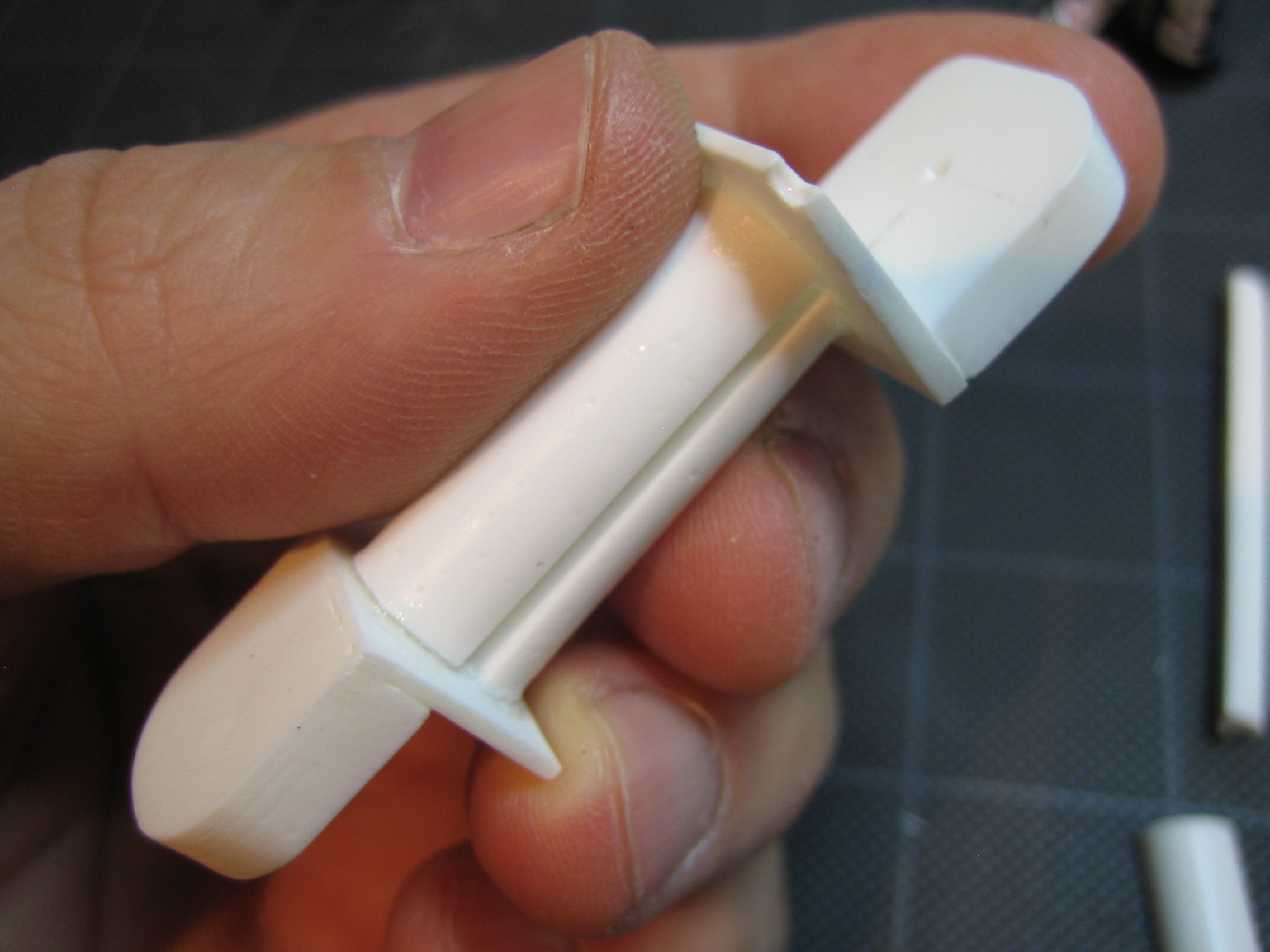
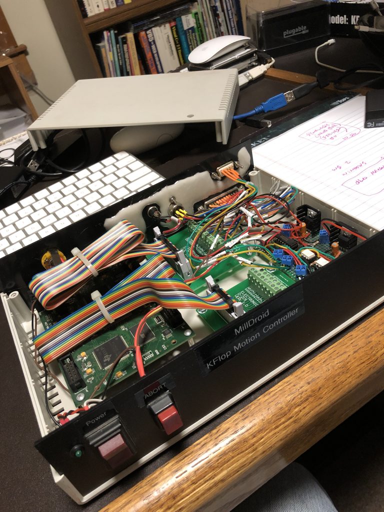
A few breakout boards for troubleshooting and some Schmitt trigger circuitry to clean up the magnetic encoders I built and internal 3.3 and 5 volt power supplies for add-ons. In 2020 I decided to build my Pendant Control for it, but the case was getting a bit crowded for circuitry. I built a new case from Styrene, using the mill to machine all the curves and holes for buttons.

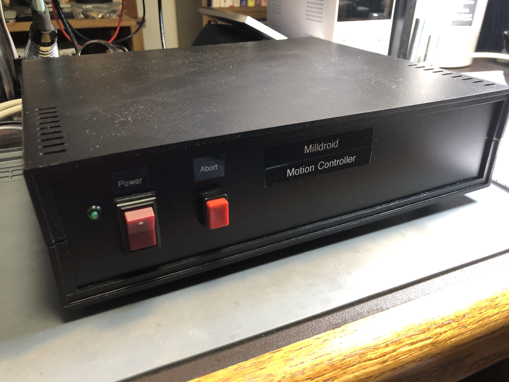
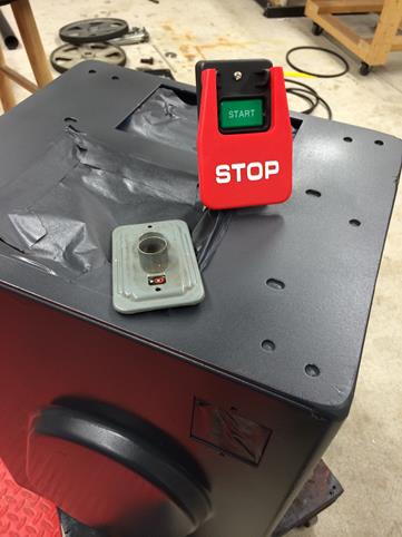
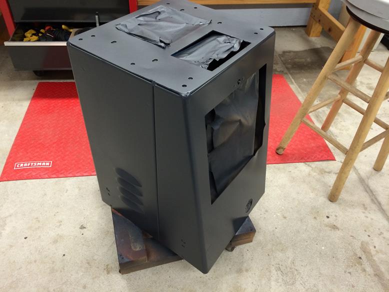
The new KFlop-Controller case. A couple inches wider, deeper and an inch taller gave me plenty of room for new circuitry, including another 32 IO ports for the coming Pendant Control and an external Abort Button. The circuitry doesn’t generate that much heat, but it didn’t hurt to have a few air vents for circulation and they look nice. I may get around to making the Abort Button wireless, but I’d probably lose it into the same other-worldly dimension to which old keys, socks and tv remote controls vanish.

Ā 

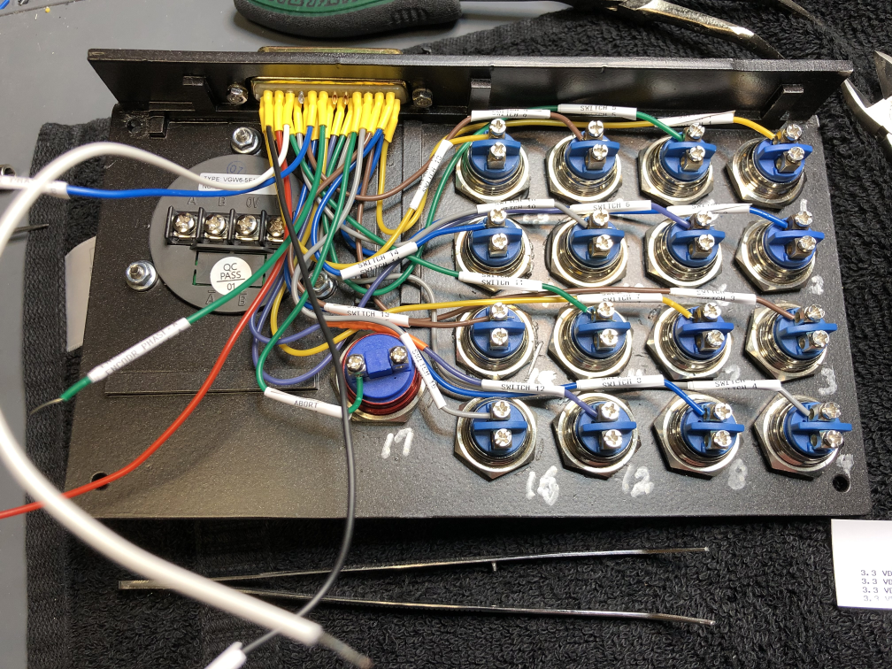
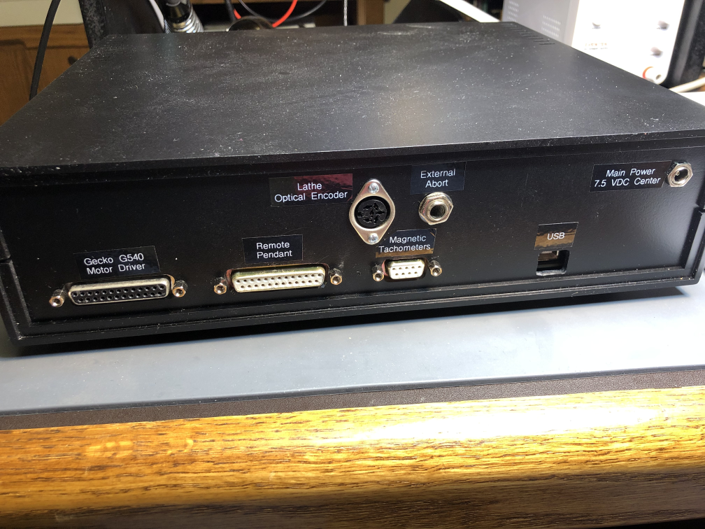
Plenty of external device connections at this stage.

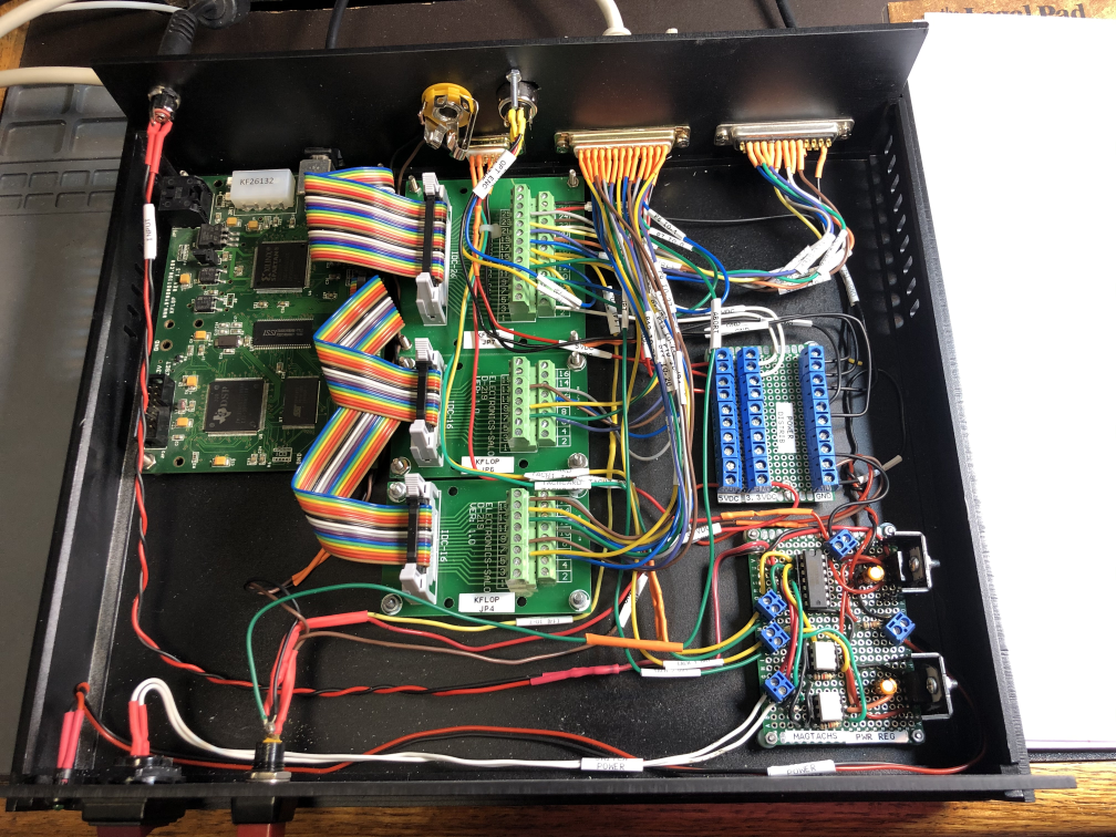
All the new circuitry, cleaned up a bit and still some room to expand later.

Ā 

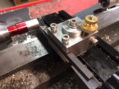
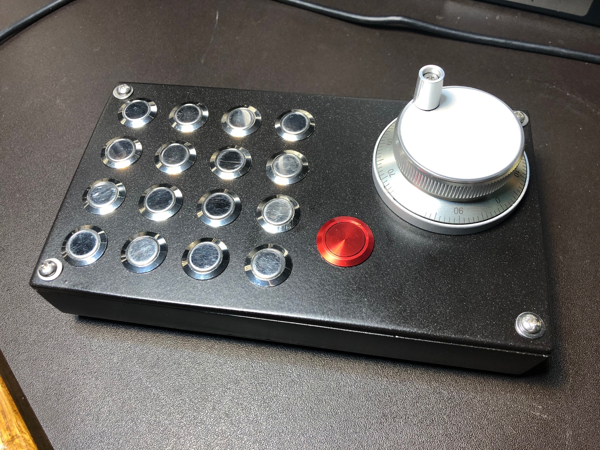
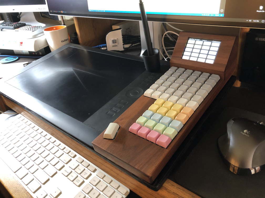
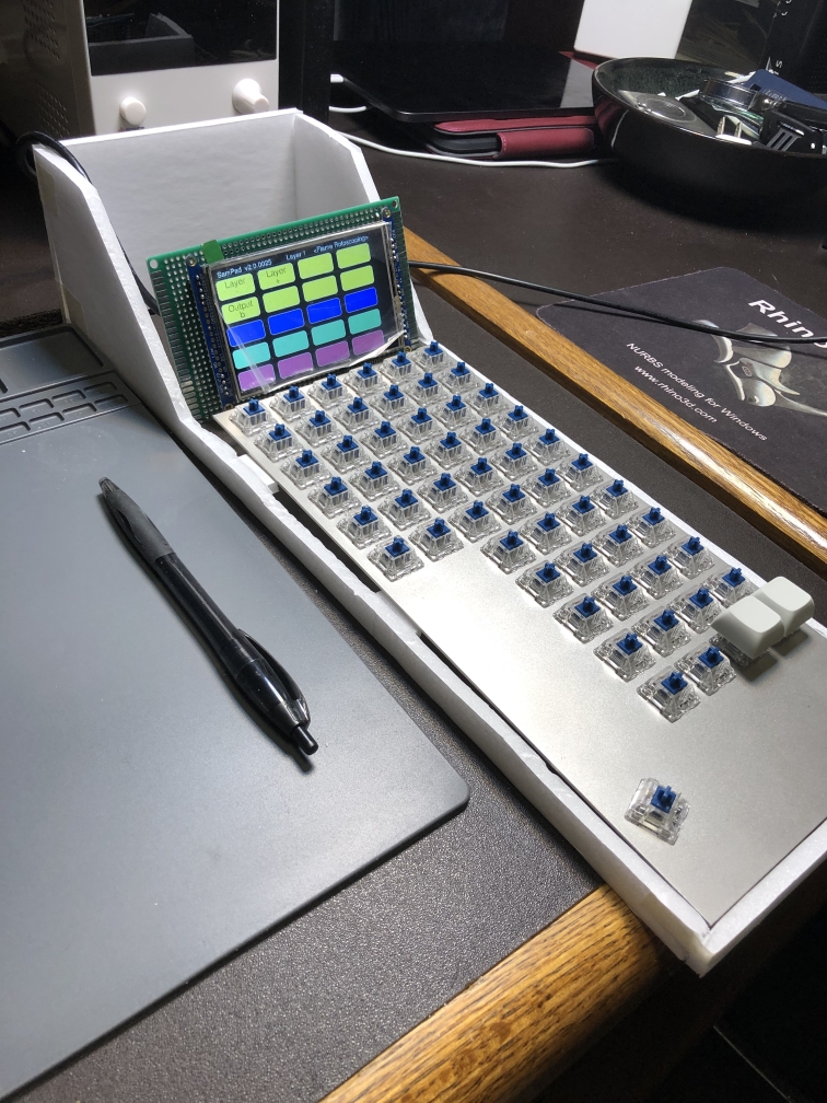
Here is a pic of the finished Pendant Control. Connected by a 25-pin cable, it give me 16 programmable buttons, another Abort Button and an optical encoder knob for precise movement of the mill and lathe without having to use the keyboard and mouse. I should have built this years ago. See the CNC Pendant Control entry on my blog for build details.

MillDroid continues to grow. I update the software almost weekly or everytime I think of something new. A few online sites have scraped my blog pages, leading to a lot of interesting speculation as to its future, availability and other things. Here are some questions and answers for those who care:

Q: Will MillDroid work with controllers other than the Dynomotion KFlop?

A: No. The application is coded very tightly around the KFlop and it’s libraries. It’s a wonderful device and I haven’t found anything elsewhere that is as flexible for programming.

Q: Is the MillDroid softwarefor sale?

A: No. I’ve written and sold commercial software in the past and the limited user base for which MillDroid would appeal does not justify the work that would go into maintaining it for others and support. It just isn’t worth it either from a time or financial standpoint.

Q: Is MillDroid’s source code available or open source.

A: No. I wrote this code for my use, to solve very specific goals I had, and in the manner in which I like to write code. Its limited user base, specific hardware needs and programming language (mainly VB.Net and some C and C#) make it a very niche application designed for programmers that like to modify their applications. If you want to write your own app I’d be glad to offer suggestions; just check out the Dynomotion KFlop user forums where there are plenty of people who have written CNC code for their KFlop (like me!)

Ā 

MillDroid CNC

My garage was little more than storage as it came with our home. Plastic lined the ceiling to avoid drips, 10 amps of power and no heat. I could only work in it during the warmer months.


Ā IMG_0009


The first thing was to clean it out–attic rafters filled with old boards and doors from the original owner, pieces of siding and junk. Because it was very rainy I was forced to continuously re-arrange the contents of the garage as I worked. That made it more time consuming. Like most remodeling projects it got worse before it got better.


IMG_0019


THAT is one ugly sub-panel. The line from the house was only 10 amps. My vacuum and saw together would blow the fuses in the house.


After ripping our every wire in the garage I re-wired it all with 20 amp electrical and all new outlets. I placed outlets on the ceiling for both tools and lighting with everything into independent new breakers. When as estimate for the electrical came in over $1200 I decided I would do it all myself.

I also foamed and sealed the entire garage to eliminate air leaks and fixes any roof leaks that actually turned out to be water coming in through wall joints.


IMG_0364

The original owner had built the garage with a two 16 foot 2×10 beams spanning the entire length of the 36 foot garage. Where the beams met in the center of the garage, the ceiling had sagged 5 inches because of this dumb design. I wedged and jacked up the center of the beams, then reinforced them for their entire 36 foot length with two more 2×10 in parallel. I glued and screwed the entire assembly together into a single tremendously strong beam. I also reinforced all the trusses to the ceiling and used hurricane braces to line up and reinforce all the other construction of the roof and ceiling.


IMG_0380


Ahhhh. Clean wiring and a real sub-panel. Loose wire is kept outside the box if needed.


IMG_0022


Wood or drywall? Every drywall garage I’ve every seen has suffered from split seams and cracks. Whether from settling, humidity changes or anything else drywall just isn’t very durable. I decided to line the shop with OSB because I liked the texture when painted. It’s durable and takes a beating. It is a shop, after all, and I was certain I’d be banging into walls and ceilings often. My brother in law helped with the ceiling–that just isn’t a one man job–then I could do all the walled myself. Of course the ceiling height was 8-1/2″ so I had do a lot of cutting using 4×8 sheets placed according. The home supply shop wanted nearly 50% more for 4×10 foot sheets and I wouldn’t throw away the money on that option.


IMG_0405


The painting. Next time I’ll buy a HPLV sprayer. It took two coats of thick oil-based Killz to primer and seal the wood which acted like a sponge on the paint. Then another two coats of white over that.


IMG_0407

A couple more coats of gray-blue along the base of the walls for contrast. Then all eight new T8 fluorescent lighting fixtures with nice white balances tubes. All of a sudden everthing seems the right color! Then replacement of the two external doors that had rusted over the years.


IMG_0436

Replacement of the original bench and all new plastic (non-rusting) shelving for tools. I found some heavy duty plastic pegboard for over the bench and cast my own resin hooks for tools.

IMG_0498

IMG_0464


Finished pics of the shop. Two wide angles of each side. Room for two cars, normal garage stuff and the complete shop in the front half of the garage. It came out very nice. Heat will soon follow as soon as the exterior gas line is run to the house.


IMG_0898


IMG_0901


IMG_1374


IMG_1376

Shop 2.0

IMG_0003

My old garage had a ‘bench’ that consisted of three 2×8 boards nailed to the wall with 2×4 legs. Wobbly and nasty. When I refinished the garage into my Shop I decided to recycle some of the wood into a new bench.

A perfectly flat bench is a necessity so aligning my sawhorses with wooden shims using two parallel strings provided a level surface on which to start.


IMG_0440


Clamped up with slight expansion joints between them, the 2×8 boards were glued to reinforcing 2x4s. These provide the structural foundation for the bench. I considered a torsion box but it would have been overkill for this project.


IMG_0441


Notching out the new 4x4s for lap joints before chiseling out the excess.


IMG_0443


Getting the legs all parallel true fast enough to prevent glue drying was a challenge. I kept moving from leg to leg with level and square over and over again to prevent clamps from gradually pulling things out of square.


IMG_0444


Since I wanted to keep the bench entirely wood without metal I bored out 3/4″ holes through each butt and lap joint. I then hammered 3/4″ hardwood dowels into each joint with glue. You have to move pretty fast or the glue will set the dowels in place before you get them all the way through the holes.

I kept the entire bench on roller platforms as it was too heavy to move without assistance.


IMG_0447


Although the bottom of the bench was flat I now had to clean up the top surface. After rotating the entire thing I filled all of the deep grooves and holes then planed and sanded the surface flat.


IMG_0451


3 coats of heavy urethane for the legs and spars and 7 coats for the benchtop. After fully curing this gives a very hard, cleanable surface for the bench. The urethane brought out the color of the wood and made the dowel joinery stand out nicely.


IMG_0459


The finished bench in place. Proper height for standing, no knee bashing support posts, solid as a rock and I can stand in the middle without it sagging!


IMG_0462


This is probably the last time it will be that clear!


Bench

I’d already made soft jaws for most of my holding tools except for the Sherline Chuck. These seemed to have tolerances a bit too tight for me but when I saw what Sherline charged for a set I decided to take on the project.


IMG_1087

The originals are made of hardened steel and dented the aluminum I was working so I would make mine from aluminum 6061.

IMG_1089

I rough cut some aluminum plate with my bandsaw.IMG_1090

I originally tried cutting a 6 inch aluminum blank, flycutting it in one pass. The aluminum was only supported by the long edges. This was a bad idea. As the flycutter passed over the center of the aluminum bar I heard a vibration–it was the aluminum bar vibrating up and down in the center! The amplitude of the vibration increased until it slammed against the flycutter and tore loose from the vise. Fortunately the carbide flycutter didn’t shatter but it dug horribly into the aluminum.

I then cut the long bar into smaller two inch pieces to make a more stable piece for milling. I was able to facemill the bad cuts out of that bar as well.


IMG_1093

Milling out the side channels with a 1/16″ end mill. Nice and slow….those little end mills break easily if pushed too hard. Plenty of air to clear chips and WD-40 to lubricate the cutter every few passes.


IMG_1097

I made quite a few “test-fits” of these, double-checking the measurements with a micrometer often because of the tight fit in the Chuck.


IMG_1098

It was a nice challenge because of the very accurate fit that the jaws required. Here are the finished soft jaws along with one of the original hard steel jaws. I actually made five so I would have a spare. Being soft, I expect to damage one at some time.

IMG_1117

Soft Jaws for Sherline Chuck

This was a tough project. I originally bid out the project to have my shop heated to several companies. 7 of 8 never returned my calls. One came back with a bid of $5,000 to put in a $1,000 heater. I was appalled at the lack of motivation and greed of these companies, not to mention the lack of professionalism. Failure to return calls was rampant. I tried again several months later with a whole new crop of companies and got similar results. I decided to do the install myself (with some help from my brother-in-law for the heavy lifting parts).

I did manage to find a local company to dig a trench and run the gas line from my home to the shop for a reasonable fee.

The biggest problem was trying to determine the definition of “code” for my city. Calls to the city inspector with questions were returned as “whatever is says in the instructions is okay”. The problem was that the details i was asking about were not in the instructions and I didn’t want to find out after I installed it that I’d missed something critical (or safe)!

Lots of research later I installed a Sterline 105 BTU heater with external combusion. I recommend it highly, although the documentation had several things critically wrong, such as reversed intake and exhaust lines on the instructions! I notified them and they have since changed it.

Since I was having the trench dug I figured I’d run some 1-1/2″ PVC pipe myself with a 30 amp cable in case I wanted to increase my currently anemic power supply. This would avoid having to re-trench again at a later date.

IMG_1068

Detouring around underwater drainage tubes and an old deck….


IMG_1064

Hanging bolts from the above-ceiling beams….

IMG_1040


Quite the jigsaw puzzle of tubing. Some came with the heater, some I had to deduce and purchase myself from a local heating and cooling supply shop.


IMG_1042

The external setup brings fresh outside air in for combustion, shielded from the exhausted nasty stuff by the big round plate.


IMG_1053


The final interior setup. Complete with a wireless internet thermostat that I can control from anywhere it works well and is reasonably quiet. The shop goes from 40 degrees F to 60 in about 10-15 minutes. I hate the orange high-heat silicone caulk around all the silver aluminum joints….I wish it was available in silver. It’s a silly thing but it bugs me…and you can’t paint silicone.


IMG_1081

Shop Heater

After much frustration clamping small parts to my drill press table I decided to make a Tooling Plate similiar to the one I built for my Sherline Mill. By using the same sizes for mounting hardware I can use holding tools on both devices without having to purchase two different sets.

photo1 4


First a trip to the local metal dealer for some good “drop” scraps. I was planning to use 14 x 18″ x 1/2″ aluminum plate but the thinnest in stock that day was 5/8″. Heavy, but good and solid for about $50. A few passes with the random orbital sander on top and the belt sander on the edges to smooth it all out yields a good surface for drilling. Remember, this isn’t supposed to be a surface plate.


Image1

The plan is to build a frame of 1-1/2 x 3/8″ bars and bolt it to the bottom of the plate. This frame would them be easily grabbed by my my XY Table. Then when I position the XY Table, the ToolTable can be (relatively) precisely placed.


photo 4


I drilled, chamfered and tapped eighteen equally spaced 10-32 holes–the same size Sherline uses for all it’s clamping devices. The thicker plate took some time to tap. Good for the forearms.


photo1 3

I also drilled and tapped several specifically spaced holes for items such as Sherline’s vise and a small precision vise I use that I previously mounted to a small plate for tiny items. This plate’s holes are set to work fit into Sherline’s T-Slots both along the X or Y axes.


photo 5

Now the frame could be bolted with more 10-32 machine screws. These were drilled and counter-bored into the table top and set just below the surface to keep it smooth.

photo 2

The finished product! It’s now easy and fast to make small positioning adjustments in both the X and Y axes when setting up to drill. It’s important to remember that the base XY Vise, being a cheap product, has lots of backlash so I always lock the vise leadscrews down before drilling.


ToolTable, Depth Guage and Improvements to Drill Press

Over my decades in the post production and visual effects business, I’ve experienced many occasions where we’ve had to name a new computer, service or application. Sometimes we would ask people’s opinions, sometimes we didn’t. I’ve kept track of some of them over the years along with snippets of the conversations that took place when names were ‘discussed’. Here are a few of them, usually with two to five people at a time responding, verbatim. You just can’t make this stuff up and it will all end up in my book one day.

ME: “We’ll name the new giant killer render farm machines after monsters from old Japanese monster movies, “GodZilla, Mothra, Rodanā€¦.Cool, right?”

Why Monsters? Why not muppets or famous wrestlers, dude? Those would be way better. Why not just Farm1, Farm2, Farm3. That’s too confusing and no one will remember them.

ME: “We’ll name the business servers FS01, FS02, etc for File Server 1, File Server 2, etc…so people can remember them.”

The Crowd: “That’s boring and not very creative. We want to look creative. Why not use names of famous people like Sinatra, Davis, Martin….”

ME: “We’ll call the temporary directory “TEMP”, so you always know it’s temporary, ok? They’re only temporary so keep them somewhere else.”

THE CROWD: (at any future time) Why did the things that were in TEMP go away?”

ME: We don’t need another temporary folder. Just use the one called TEMP”

THE CROWD: “We need another and it should be called TEMP2. But it will be permanent.”

ME: “Isn’t that what everyone thing else, besides TEMP, is already?”

THE CROWD: “No, that isn’t clear enough. How about renaming the old TEMP folder JUNK. NO! How about STASH or GLOVEBOX?”

ME: “We’ll name the new media servers after pop culture waitresses, like Alice (Brady Bunch’s maid), Rosie (the Jetson’s maid), etc. Get it? They were all servers, right?”

The Crowd: “No one will ever remember those. Why not make ours Graphic Server and the other one Edit Server…?”

ME: “We’ll just name the backup server “Backup Server” because that’s what it is and does. Easy, right?

 The Crowd: “How are we supposed to know what it backs up?”

ME: “We’ll call the new universal encoder application nCode? Get it? nCode? Clever, right?

THE CROWD: Person’s eyes roll back into there head as they think ‘geek’.

ME: “We’ll call the app that manages all the jobs JobManager. Perfect and no doubt about what it does!”

THE CROWD: “Couldn’t you come up with a better name than JobManager? Not very exciting.”

ME: “We’ll call the Houdini Render Controller “Harry”. Get it? Harry Houdini?

THE CROWD: “Harry is a dumb name for a program.”

ME, a year later: “Since the Render Controller can now render things other than Houdini, we’ll call it “UltraRender”.

THE CROWD: “Can’t we just leave it as Harry? We want it associated it with Houdini?

ME, years later: “We’ll call NEWEST render controller “Miranda”, after the character in Shakespeare’s “The Tempest” who watched all the ships from the attacking fleets crash into the rocks!”

THE CROWD: “What? Why can’t it just be called RenderController?”

ME: “We’ll call the new media server Kong, because it’s a giant monster bigger than anything we’ve ever had before.

THE CROWD: Why Kong? Why not just “Server”? Why not “GraphicsServer”? Why not “Jobs”?

ME: “What should we name the new Media Library application?”

THE CROWD: “Who cares what it’s called?”

ME, later: “We’ll call the Library Application Emily, short for Electronic Media Library”.

THE CROWD: Why Emily? Who’s Emily? Why not Library? Why not DAM? Who came up with Emily?

THE CROWD: “I really think this (JobPortal Server) needs a name. You know….like ‘Kong’…..but not like ‘Junk Drawer’ “

ME: sigh.

After a while, we stopped asking people for name suggestions. A former president once said to me “Questions I know the answer to, I don’t need to ask, right?”

What's in a name?

My full height Craftman Drill press was in need of some attention. It had always had some wobble and vibration issues. The depth guage was very innacurate as well. I started by removing all the pulleys and the tension arm.IMG_0976

A medium sized gear puller made short work of that task. I then scrubbed the painted pulleys in mineral spirits and cleaned out all the old grime and grease. Upon closer inspection I found a lot of rough edges on the pulleys that might have been snagging on the belts at times. I filed the pulleys in several places to smooth them out, then after cleaning resinstalled them with some new lubrication.IMG_0979

The tension arm shaft ends seemed a bit rough so I wet sanded it a bit smoother. After reinstalling the belts a test showed that this fixed most of the vibration issues.


The drill press had arrived with the arbor and chuck installed. I had never had reason to remove it so i had to dig around to find the original arbor removal tool. Fortunately I found it deep in my tool collection. Very little rust even after 17 years of use. I polished up the arbor and gave the chuck some fresh oil to prevent rust as I do a couple times a year.IMG_0980

The original power switch as installed was a PITA. It was always locking up on me. I removed it and installed a heavy duty toggle switch with a thick plastic backplate. Better.

IMG_0981


Now for an accurate depth guage. I purchased a 6″ digital caliper from Harbor Freight for $15, then set about milling some 1/8″ aluminum angle and sheet into a couple brackets for mounting. IMG_0982

I drilled and tapped two 10-32 holes into the original depth guage’s mounting block. This is where the flat plate would attach for the “fixed” part of the caliper. The angle plate would attach to the bottom of the bolt on which the original depth guage was etched.

My original intention was to drill and tap mounting holes into the caliper. I attempted to drill holes into the caliper’s arms. Not a chance. That hardened steel was impervious to my drills. I switch to my Dremel and a grinding wheel and ground out notches for the screws. Not the prettiest but it worked and would be hidden by the mounting plates.


IMG_0983


No, that isn’t blood, but marking dye.

IMG_0987

I used some stainless steel machine screws, washers and bolts to tie it all together. I hate rust.


IMG_0991

I also ground off the sharp “inside arms” from the caliper after the first time I cut myself on them. Sharp little suckers. The caliper adds a bit more friction to the drill press so I had to adjust the tension of the quill spring to be a bit tighter. Otherwise releasing the quill are would fail to withdraw the chuck from the work. It was a little like balancing a garage door spring for the tiny amount of added load.


It works great! I zero the guage after drawing the drill down to the top of the work and it’s only a button press to switch between decimal, metric and fraction on the fly! I kept the original depth guage purely for it’s continued use as a stop to prevent accidentally drawing/drilling too far and wrecking my future drill press table I intend to build.


ToolTable, Depth Guage and Improvements to Drill Press

I made myself a couple thin Sine Plates for my mill. Set angle plates looked like a good idea at first but it seemed like I needed something that would “hang out” past the sides of my small vise for easier setup. I copied the general look and feel of most of the commercial bars. Milled from 1/8″ 6061 aluminum plate I wrote the GCode for the 3″ and 5″ profiles and milled them.IMG_0994


I decided to make a 3/4″ thick bar version while I was at it.

IMG_0995

Sine Bar and Plates

These seem to be many machinists first project. Most are seem to be made from raw stock on a lathe but since I’m without that tool I cheated. I bought a few stainless steel hex bolts, nuts and long thread couplers and cut them to length with a Dremel & grinding wheel.


IMG_0998

I then milled the tops and bottoms of the newly cut couplers and the tops of the bolts flat with a face mill and polished the surfaces to a shine. Nice little tools for an hour worth of work!


Machinist Jacks

Most of the hand sanding that I’ve done while in the process of finishing metal has been on a makeshift surface plate. I had found a few marble floor tiles that were remarkeably flat–close enough to a Grade-B surface plate to be usable for most of my projects. I polished out any imperfections that were objectionable and I “grade” them with a magic marker on the back so I can use the best when more accuracy is demanded. They have worked very well and for $4.00 are a great value.

IMG_0967

Usually I would place the tiles on my flat bench within an old cookie sheet with a squirt bottle of water, washing away dust as I worked. Since I’m spending a significant amount of time doing this I thought I’d come up with a better method.


I recently found a local metal source that has boatloads of “drops”. These leftovers from large cutting jobs are a great deal for a hobbiest such as myself and are usually priced much lower than it would cost anywhere else without even including shipping. With a large assortment of aluminum, steel, brass and bronze I can’t imagine going anywhere else now. I picked up several 12 x 36 x 1/4″ 6061 aluminum plates for a several dollars each with the intention of building a wet sanding station.

IMG_0965

I cut the sheets into three triangular rib plates, a cross brace and a backplate, then notched the backplate to take the verticle ribs. I used stainless steel machine screws and tapped all the holes 10-32 to match with my drill press. This gave me a very strong skeleton on which to place the flat tiles.

IMG_0968

Lots of edge holes to drill and tap but it was the cleanest method of mounting everything together without having to use any ugly brackets. Had to always remember to use non-rusting fasteners since this project would be under water often.


IMG_0971

The notches dado-like mounting made the ribs very strong even without the 10-32 machine screws. The four empty holes were to allow the plate to be mounted to my Sherline Mill for all the slotting and milling. It was no easy task coming up with a method to make the 8-inch slots on my mill. I had to cut half a slot’s length, then reverse the plate on my mill and cut the other half. Precision mounting was required to avoid any drift in the cutting and it all worked out well although it was quite the mental exercise.


IMG_0996

The aluminum framework is then placed into a plastic restaurant bus tub. I mounted a small garden water pump and routed it to some bendable Loc-Line to allow routing the water stream where it was needed. The pump is the type that can handle sediment and crud and seems to have no problems with the metal dust I generate when tested. For $20 I didn’t expect a lot but it performed well.

IMG_1001

It works! Now all the metal dust is not only kept out of the air but is washed off the sandpaper as soon as it is created. It’s a noticeable difference during use and has cut down on scratching that happens as the sandpaper clogs. This happened a lot with the finer 500-2000 grit wet paper I’ve been using. Now I’m seeing much better results. This project falls under the category of “why didn’t I do this a long time ago?”

IMG_1004

Because the water pump is pretty weak, about 1-2 gallons per minute, the Loc-Line “Fan nozzle” doesn’t spread the stream as much as I’d like. I might have to flatten it a bit with a little heat to get the stream to widen to the entire width of the paper or make my own custom nozzle. It works fine as it is but it bugs me a bit. I could leave it alone.


….Nah.


Wet Sanding Station

IMG_0944

As my number of automated mill processes increased I began to realize that I needed some automation in the clean-up department around the spindle. Although I don’t wander away from the mill very far when it’s operating, blasting compressed air at the cutter by had gets old (and tiring) after 20 minutes or so. I already had run a compressor line and drop to above the mill for hand-use so I split it into a second line for some automatic use.


I squared up a piece of 3/4″ 6061 aluminum bar stock with the intention of creating a manifold for the mill. I drilled out the interior of the stock with an appropriate drill for a 1/4″ NPT tap that would match all my compressed air lines. I tapped the end of the hole. I then drilled and tapped two 1/4″ NPT holes in the side of the bar for Loc-Line flexible hose. I drilled and tapped two 10-32 holes into the Sherline mill’s Z-Axis spacer being very careful not to clip the internal key slots or center alignment pin. Two 10-32 counter-bored holes in the manifold and machine screws hold the manifold to the mill securely, raising and lowering the air lines in sync the spindle. By using a coiled air hose to feed the manifold from my ceiling air line, everything stays safely out of the way of the z-axis hardware. I only used two Loc-Lines to blow air to the table, but there is room enough for four more on the manifold if I ever needed them. At the start of the Loc-Line I included their variable adjustment to allow me to feed each blower with a different amount of air. A ball-valve at the manifold intake allows me to quickly enable/disable the entire system without losing my pressure settings that I’ve already made on the Loc-Lines.

Air System for Mill


IMG_0949


I wanted to make a tooling plate for my mill to give me more versatile holding capabilities. I thought this would be a good project to practice my drilling. After experimenting on my drill press with some scrap I learned a lot about wandering and peck drilling. Like most of my projects this one led to another project: A PeckDrilling plugin for my CNCDroid software.


After truing up some 3/8″ 6061 aluminum stock with a facemill I proceeded to test out the new software. It was a good project to play with for things like dwelling at the bottom of a drilled hole and how far to actually peck and wait before returning the swarf to the top of the hole. It also made me start thinking about some type of directed airflow/blower for the mill as I was continuously hovering with my airgun to blow away the chips from the holes.


Eight 10-32 counter-bored holes give lots of table mounting options for T-nuts, and twelve threaded 10-32 holes give ample locations for clamping screws. To keep the threaded hole free of swarf I keep them plugged with twelve inset machine screws that are only removed when the tooling requires it.


IMG_0951


On the bottom of the plate is a 3/8″ aluminum bar mounted as a reference for the mill table edge. This allows for very quick alignment of the Tooling Plate to the X-Axis table of the mill without having to measure. Along the bar are two inset 10-32 machine screws that are used to micro-adjust the plate into exact alignment to the table top. A drop of loktite keeps them from drifting.

UPDATE: I’ve been using some A2ZCNC T-Nuts for this and other projects on my Mill. Of the 12 I bought, I’ve bent/broken 9. Everyone of the TNuts from my original Sherline purchase is still in great shape. I would advise against purchasing the A2ZCNC T-Nuts. Yes, they offer to replace any that break, but why bother with that high a failure rate?


Mill Tooling Plate

IMG_0953

I duplicated my Sherline Vise’s existing steel jaws in aluminum 6061. This set of soft jaws is perfect for me since the majority of my work is in aluminum. I matched the dimensions of the steel jaws and their 90 degree grooves, then copied the drilled and threaded holes to match.


SoftJaws for Sherline Vise

IMG_0941

Another great idea of Dave Hyland’s that I duplicated. Unlike my other low-profile vise, this version allows clamping in the Y-axis as well as the X. It also allows for clamping much wider objects for greater stability with thinner materials. I used this project to iron out some kinks in my CNCDroid program’s SlotCutter plugin, including counter-boring the slots. I’ve started to notice some rust on my collection of black oxide machine screws. I think I’m going to start using all stainless steel screws from now on. The brass washers add a nice bit of color to all the aluminum 6061, which I left with a facecutter-induced polish.

Update: A fellow metal worker suggested I add a small slot along the fixed jaw to allow for rough edges and debris. I picked up a couple 1/16″ endmills from a local shop for $1.50 each (I had a feeling I’d break at least one at that tiny size!). I then milled out a 1/16″ x 1/16″ relief slot. Better!

IMG_1007


Another Low Profile Mill Vise

IMG_0955


A YouTube video gave me the idea for this one….an online Sherline Mill user had something similiar that allowed objects to be held on the mill table without raising them up high. This allows more room for tooling and eliminates having to use larger parallels in a normal sized vise.


I milled and counterbored the four pieces from 6061 aluminum. I used a 1/16″ endmill to SLOWLY mill out a 1/8″ x 1/16″ relief slot for debris and rough edges. Those little endmills break very easily. Afterwards I brush-finish sanded it all to a dull luster to help hide the scratches that I knew would be forthcoming.IMG_1009

To keep the adjustment screw from damaging the aluminum I drill a slightly undersized 3/16″ hole 1/8″ deep at it’s contact point on the spacer bar. I pressed a 3/16″ hardened stainless steel ball bearing into the hole and left it protruding by 1/16 of an inch. This give a durable press-point for the adjustment screw to press against.


Low Profile Vise for Mill

IMG_0922

After I completed restoration of my bandsaw I needed a method of cutting smaller pieces while still keeping my fingers. I milled down some 3/8″ aluminum plate into a sliding table similiar to that used on a table saw. Some anodized miter bar and a few 10-32 machine screws counter bored into the surface kept everything together. The miter bar has two inset 10-32 screws to allow for precise alignment in the miter slot. I use a couple 1 and 2″ c-clamps to mount small pieces of metal to the cross member during cutting. It’s a very useful addition to a bandsaw and keeps all cuts at exactly 90 degrees.

UPDATE:

I drilled and tapped several 10-32 holes into the sliding table. This let’s me use my mill clamps to hole pieces too small to safely hole with my fingers.


IMG_1122

Sliding Table for Bandsaw

IMG_0937


After seeing Dave Hyland’s Vise Stop I decided to duplicate it. I machined it out of aluminum and brass. I’d never worked with brass before and I really liked the look of the brass/aluminum combined. I soldered the brass knobs onto steel threaded rod for the screws. I knew it would see a lot of scratches to I finished it with a couple decreasing grades of wet sandpaper to give it a “Delorean” brushed look. It works very well, but I noticed that it’s only useful if the milling is being done on a piece that fits within the boundary of the vise. I may have to make an alternate version for larger-than-vise objects….or perhaps make a new stop for the mill table itself.


IMG_0938

Stop for Sherline Vise

My vice has toothed steel jaws that were scratching and denting the aluminum parts I’ve been making. I considered making a set of aluminum replacement jaws but realized what a pain it would be unscrewing and re-screwing the four screws to switch back and forth. I had seen someone create a set of soft jaws with embedded magnets so I set out to make my own.


I purchased some1/4″ neodymium rare-earth magnets at a local crafts shop. Then cut some Ā½” aluminum angle that I had in the scrap bin and thickened one side with some Ā½” aluminum bar to accommodate the magnets. After drilling holds to accommodate the magnets I used JB Weld to epoxy them into place. A little cleanup with files and they snap into place quickly and easily!

SoftJaws for Bench Vise

Once I started toying with metal in the shop I encountered the need for more serious cutting tools. I had been cutting aluminum with hacksaws and my old craftsman saber saw. I built a jig for holding aluminum bar and square stock and bought a new Dewalt saber saw that was a large improvement but it was still pretty tedious and innacurate.


I spend a few months researching online and came to the conclusion that I should invest in a bandsaw. I wanted something that could handle wood and metal with variable speeds. New I was looking at around $2000. Further research and online discussions led me to see that the new saws are really just cheaper-made versions of saws that were made 20-50 years ago. As one online machinist put it, all improvements for tools like this happened a long time ago and after that it was all about cost savings. It appears he was right as the amount of plastic and cheap parts in bandsaws today demonstrates. The “dream bandsaw” for a lot of online machinists in my hobbyist situation seemed to be the 1959-1974 Delta Rockwell 28-300 Metal/Wood Bandsaw. It had everything you could want in that category of saw. Ebay and Craigslist searches proved itā€”The few that did appear were sold within short amounts of time and went for over $700; sometimes in terrible shape. After several aborted attempts to buy one online I discovered that the company I work at had owned one and given it to a coworker. It was a stroke of luck and exactly the model I was looking for. I purchased it from him for $400.


It had been kept indoors unlike a lot of the ebay saws and was usable as it arrived but I really wanted to restore it to its former glory. This tool was 54 years old. It had not been kept particularly cleanā€”wood and metal dust on it had hardened to a resin-like consistency. The gear box oil had never been changed and the gear box wouldn’t switch gears without being priedā€”something that had been done in the past and damaged it. This crud needed to be chiseled off.


First up would be complete disassembly and cleanup. Purchasing a gear puller to make removal of the pulleys and gearbox components easier would help, as would some auto tools such as spring loaded clip pliers.


I used a lot of penetrating oil to cut through the gunk enough to be able to pull off the components. It’s amazing how hard the caked on sawdust and metal combined with 50 years of oil and moisture can be.

Disassembly was not an easy task. The entire saw is HEAVY, probably around 400 lbs. Even in pieces some are too difficult to move without help. Holding a heavy part so it doesn’t fall while working the tools on it was not easy so in some cases I used chain to hold a piece up while I removed it.


Careful arrangement of the parts to avoid misplacing them.


Surprisingly the blade tires were in good shape. No damage, just dirty and after a good cleaning were still useful without having to be replaced. That saved me about $60!


The table had a fair amount of rust that I removed with some Simple Green, phosphoric acid and elbow grease. Gradual sanding with a granite block and dry then wet sandpaper cleaned it up nicely followed with immediate paste wax to prohibit future rust. Every adjustment knob of the table & trunnions was “frozen” in place from lack of maintenance. I took apart every nut and bolt in the system then soaked and brushed them with acetone until spotless.


The gearbox handle, frozen in place from being pried into position with a steel file. This part of the operation scared me the most since there were over 25 parts in there and no documentation. I was very nervous about getting it back together afterwards.

This bandsaw model is unique in that it has a gearbox capable of lowering the speed of the blade to the slower ranges required for cutting metals. There were a couple online examples of people working on the same gearbox but they were always missing the “in between” steps for assembly. It was definitely a learn-as-you-go type of thing. I was careful to label and arrange parts on my benches as I dismantled them. I did make the mistake of labeling some parts with marker only to realize that when cleaning the part I washed off the label. Ugh. Practicing assembling and disassembling the entire thing a few times helps to keep it fresh in your mind and become more of a reflex.


After draining the oil from the gearbox and letting it drip overnight I started removing everything. The oil was pretty thick after 50-plus years of use. I cleaned each part thoroughly with a mixture of Simple Green to degrease it and remove overall dirt, then acetone or mineral spirits depending on the makeup of the part.


Once the gearbox was drained of the old oil I scrubbed it and its components with acetone and washed them afterwards. Since these steel and iron components have been immersed in oil their entire lives they can “flash-rust” if cleaned and left exposed to air for even a brief amount of time. To minimize this, I kept the components in sealed zip-lock bags until it was time to clean them. Immediately after cleaning I coated them with fresh oil and resealed the bags to keep exposure to oxygen to a minimum.


The gearbox is just large enough to get your hand into but still difficult to work within. The razor-sharp metal edges from the original castings signed their name into my hands a number of times.

The gasket for the gearbox had decomposed pretty badly but surprisingly it never leaked. I purchased some new rubber gasket material at a local auto parts store and traced the gearbox onto it to cut a new one.


The oil was the consistency of epoxy in some places. It took a lot of soaking and brushing to get the old oil out of the system. I wore out several old toothbrushes!


Small parts all cleaned and reasy for assembly. My Tablesaw doubles as a workbench for projects like this.


The gearbox main shaft reassembled. 25 pieces in all. I repaired some severe scratches and dings that were preventing shifting between metal and wood blade speeds. Careful filing and wet sanding made it better than new as you could shift speeds with your little finger and almost no pressure. In fact, I later discovered that it was TOO easy to shift speedsā€”the machine could now drift from one speed to another without pushing the shift knob! I roughed up the surface of the shifter shaft a tiny bit to fix this.


The steel base of the saw had some severe surface rust around the bottom and corners. I removed this with a power drill and wire wheels, grinding off everything that was loose through the paint. Then I power sanded down to bare metal areas around the rusted zones. Structurally it was fine and the motor was in great shape and ran smooth. The power switch was original and difficult to adjust so I took the opportunity and rewired all the internals and replace the switch with a safer version for a power tool.


I then masked everything off and painted. The base I airbrushed with a dark gray/blue custom mixed from various Rustoleum enamels to get the color I wanted. I really like the Rustoleum brand and it dries very hard to provide a lot of protection. It does need to be thinned a bit to get through the airbrush smoothly. It was important to me to preserve the original metal labels on the saw.


Five coats airbrushed on with drying time between each. It’s important to let the paint cure for a week or two after drying to avoid easily scratching it while assembly.


The cast metal parts I brush painted by hand. Because the brushing can be done with thicker, unthinned paint only 2-3 good coats are required.


Reassembly begins, from the ground up since it will get heavier as I go. This is when I realized how difficult it would be to move once put back together. In another bout of “sub-project” I stopped on the bandsaw to build a heavy duty wheeled base for it. Some painted studs and heavy locking wheels later I had a base to build upon.


After carefully reassembling the jigsaw-puzzle-of-a-gearbox I purchased two quarts of 85W-140 gear oil and filled the gearbox, watching carefully for leaks. Not a drop (whew)!


I reattached the pulleys, rear shields and tensioning apparatus hardware.


The wheels went on next. The original bearings did not need to be replaced which was nice because it saved me about $120. The covers I painted a different color to stand out a bit. The saw was missing it’s original Fence. After a bit of research I purchased a Kreg bandsaw fence. It fit the saw perfectly and was highly recommended, not to mention it was a cool blue anodized aluminum!


During assembly I dropped the gearbox housing frame onto the concrete floor of my shop. Two of the welds in the steel broke. A friend repaired it for me with a little welding and after some more paint I reinstalled it. The metal clips that originally held it to the chassis were missing so I drilled some holed and bolted it into place properly.


One of the original belts was missing. This model can operate with both belts on at the same time as the gearbox shifter determines which belt is in use for all but two speeds. No matter what I tried, I could not get the motor tension set so that both belts would be set properly at the same time using the recommended belts. I switched from a rubber belt to an adjustable link-belt for the second one in order to finesse the size until it worked perfectly. The link belts are more expensive than they should be but worth it to get a proper fit. Contrary to popular belief they don’t seem any quieter than a normal belt. I think that’s a myth started by someone who had old belts that were “set” into place, then “throbbed” as they hit their flat spots on the way around the pulley and caused vibration.


I picked up a new bi-metal 8 TPI blade for the saw as well.


Another project-within-a-project: To cut down on the amount of dust and metal chips getting everywhere I created a “debris catcher” for the bandsaw. It seems like 90% of the debris is right after the blade cuts the material (naturally). I roughed out with cardboard and box around the blade immediately beneath the table. It encloses the blade almost entirely where it exits underneath the table and bolts into place. I then traced the cardboard onto 1/8″ acrylic sheet and welded it into shape with acrylic glue. Nasty stuff, that acrylic glue, but not as bad as MEK cement. I attached a rubber adapter for my shop vac to suck out the debris during use.


The vacuum attachment works GREAT! Very little debris makes it past. The little that does falls out the bottom of the bottom blade cover and is easily swept to the floor. It does make me want to build a quieting enclosure for my shop vac!


I’m extremely happy with this project! It runs as well or better than any bandsaw I could have purchased new and cost me about $150 in parts not including the fence. It is very quiet and has been cutting metal like a dream. I learned a lot during this project and am considering restoring some other older tool because of it.

Bandsaw Restoration

The final arm in it’s display case home. Several hundred parts in total and almost two years from conception to completion. In addition to the arm, I built and completed my wood and metal shop and gained quite a few new tools. I also restored quite a few as well, and every one was a learning experience. I also wrote quite a bit of custom software for the mill, lathe, and other items for the shop. I’m mighty proud of what I created and learned along the way considering that when I started I had few metal-working tools beyond a hacksaw.

8-Final Work

Originally I planned to make a display case identical to the one that Miles Dyson admires in the vault Terminator 2. It looked as though it had been made from metal and glass, but I was unable to machine a large enough piece of metal to match it for the base, so I decided to go with wood and plexiglass.

Some 1/8″ and 1/4′ plywood would serve as the foundations for the base and lid. Plywood ribs added some structural stability to the cylinder-like top and bottom.

Epoxy was used to glue all the wooded ribs and rings into the rough shape.

Once the top and bottom cores had dried, I wrapped both pieces with 1/64″ plywood bent to the cylindrical shape. Again, epoxy was used to hold this skin onto the ribs.

After some sanding, I used wood filler to fill in any large gaps and seams.

Hardware of blind nuts was epoxied into place and then reinforced with plywood. Then the entire interior was reinforced with fiberglass cloth and epoxy for strength. This gave the once-flimsy 1/64″ outer plywood skin a metal-like solidity.

There were actually four wooden pieces to the case: From left to right the base, the shoulder for the top, the shoulder for the bottom with holes for the arm cabling and the top. The smaller holes in the shoulders are for 10 small LED spotlights that would iluminate the arm from within the case.

I decided to engrave a nameplate for the arm using my mill and some engraving bits. Once again, my MillDroid software provided the layout and CNC control.

I purchased a 10-inch diameter, 36″ length of 1/4″ plexiglass tubing. After a few practice cuts I fire-glazed the edges to get a clean edge. This is when I goofed–I overheated the edge, and caused one end of the tube to shrink by about a 1/4″ in the overall diameter. It affects the outer three inches of the tube, ruining the piece and forcing me to purchase a second tube and start over. I was much more cautious and the second tube came out perfect. It was a $60 mistake that bought me how quickly the heat of a torch can melt expensive plastics.

The two shoulder pieces are now painted and mounted to the top and bottom of the case. The finished wood pieces were finished with several coats of thinned wood filler, sanding sealer, then shellac with lots of fine sanding between each. A couple coats of enamel primer and three coats of nickel satin paint then three coats of satin clear coat. The shoulders where then wrapped with a 1/16″ inch layer of gray hard foam. This brought the shoulder diameter up to just slightly larger than the inner diameter of the plexiglass tube for a snug slip fit.

The case awaiting interior detailing and wiring. On the right you can see the $60 mistake I made on the first tube attempt. Ugh. Hope to find a use for is someday.

I didn’t take any pictures of the interior wiring. It consisted of a couple of 1/8″ power jacks (one for the top and once for the bottom) and some small LED “Projectors” that I machined from styrene and metal to emulate the look of the arm’s mechanics. I alternated blue and white LEDs to get a nice lighting arrangement on the metal of the arm.

7-Display Case

Assembly was hardly a start-to-finish process. I would test fit a group of pieces, say of a single finger, then pull it all apart and make adjustments. Something this was a bit of filing to make an axle a bit smoother. Sometimes it would involve polishing a piece a bit more or removing some burrs that were missing during finishing or tumbling. On average I would guess that everything was assembled at least 3-5 times each before dismantling it all before final assembly. I then literally ‘dunked’ all the pieces into an aluminum protective coating to prevent oxidation. Stainless steel parts were similarly protected by oiling or teflon lubricants. After a couple days hanging and drying final assembly could begin.

I used my Panavise to hold the palm plate and began attaching the skeletally completed fingers to the metacarpals. A bit of finessing for a good fit was necessary for each joint along with proper lubrication and remembering to add all the teflon washers I has made to reduce friction. If I had not been so concerned with matching the original arm construction, I would have probably made a change regarding the joints of all the moving parts. As they were originally made, the tightness of the cap screws of each joint determines how tight the joint actually is for movement–this is fundamentally a bad design and why I had to make certain I didn’t over-tighten the joints and bend the metal pieces and cause too much friction. A better design would have been to make some bronze or brass bearing sleeves for the interior of each joint that would prevent over tightening. As it was, I relied on red loc-tite for hold all the cap screws in their permanent positions and thus remained true to matching the original look.

More fingers being mounted, the thumb and all the interior pulleys awaiting cabling. The thumb pivots around the base of the wrist plate, consisting of a cable (for tightening the thumb joints) and a rotating sleeve around the cable (for rotation of the thumb). The orinal props thumb has some design limitations over a real thumb, but accuracy was everything for this project.

I used some tiny paint brushes to apply teflon lubricant and loc-tite where necessary. The areas for application were too small to get into with the bottles and applicators. I avoided silicone lubrication so I would not have any contamination issues with the aluminum protective finishes. Once you get silicone onto a project, it is almost impossible to clean it off short of scrubbing and soaking the part in acetone. Better to keep it out of the shop entirely unless absolutely necessary.

Muscle cables and sheaths being installed. I spent a good amount of time looking for stainless steel cabling stranded cabling that was strong enough and flexible enough to bend around the joints and pulleys yet look the proper diameter of that in the film. It turned out to be an impossible task for a couple of reasons. Cable that looked thick enough in the closeups of the arm could not have been flexible enough to use in the ‘moving arm’ that flexes at the end of Arnold’s arm in some scenes. The conclusion was that the two different scenes had two different props. Since I wanted visual accuracy over movability, I chose the thicker of the cabling choices. The joints could still be pulled and released somewhat, but it would never be as ‘animatable’ as the motion prop that was used in that scene. The sheathes for the cable tool nearly as long to locate. I found a company that made the sheaths for mountain bike brake cables that were encased in rubber. Underneath, they were a nice stainless steel (to help avoid rust) and looked perfect. Some interior lube and threading of the cables and I had my “muscles” ready to be threaded in and around all the pulleys’.

Ajusting the tension on the cables against the springs that were in all the pistons to achieve a nice ‘balanced’ look and feel took some tweaking, but it was really satisfying to be able to pull a cable from in the base of the forearm and finally see a finger flex and pivot. At this point it was starting to feel like a completed project.

A closeup of the fingertips

Here you can see the dual sheaths for controlling each finger at their bases. In this photo the cables are not yet threaded through the sheaths and pulleys, nor are the ‘palmer pistons’ installed on the empty lugs that would pull each finger down.

A closeup of the wrist plate, showing the three smaller ball joints at the end of the forearm pistons. The palmer piston are in place here, pushing against the palm to straighten each finger. All the finger cable sheaths continue down through the wrist plate and through the forearm to the elbow region. As the cable sheaths began to multiple I worried that the amount of parts in the forearm would be too dense to be contained in the allotted space and still allow movement and ‘good looks’. In the end it all fit. Barely.

Trying to crawl away towards Sarah Conner, methinks.

Here you can see some of the detail on the back of the hand and the side pistons for each finger. These spring-loaded pistons, along with a counter cable/sheath on the opposite side, cause the lateral side-to-side movement of each finger, similar to you you cam spread your singers apart.

Details of the base of each finger. The lateral cabling is not attached in this shot and one of the sheaths is not attached.

Details of the palmer pistons mounted to the lugs on each finger to push them into their straight positions. Cabling is present in this image.

Closeup of all the cable sheaths in place. You can see where, along with all the pistons, the area at the base of the wrist plate becomes quite congested with moving parts.

Forearm showing the three large pistons and ball joints for pivoting wrist movement. Lots of tiny set screws visible for adjusting and locking the springs and ball joint pieces in place.

6-Assembly

Knowing that I was planning build a CNC milling station I set about building a bench for the system. I framed a bench from 2x4s. For this bench I used all biscuit joinery for the added strength but without the added labor of lap or mortise & tenons. Besides, most of it would be covered up. Love those Bessey clamps!

I covered the top with a nice piece of single-sided birch plywood. After three coats of sanding sealer and a mineral spirits wipedown to avoid dust, I coated it with just under 1/8″ of Bar Epoxy to give it a very hard, glass-like finish. You have to spend some time making ‘dams’ out of masking tape to prevent the epoxy from dripping off the edges but it was worth it. It came out really nice. I purposely left the edges of the table 1/8″ wide because I expected the epoxy to adhere to the masking tape in a meniscus…..the overhang meant I could sand off the ledge and get a perfectly level edge.

Shop Projects

As I generated more parts, the sheer number of pieces became difficult to track. While I could stamp some larger piece with alphanumeric stamps and a hammer for later identification, tiny pieces were more difficult to identify. Combined with the fact that some tiny parts existed as ten to twenty pieces that might look identical but have slightly different measurements each. Many times I would set something down, then need to come back and re-measure fifteen or twenty pieces to find the one I had misplaced. I started a ‘bagging’ system of tiny kitchen zip-lock bags, labeling them similarly until I had enough parts to group entire sections such as “index finger” or “thumb. After that I reorganized everything be group for final assembly.

The first ‘pass’ of organization into similar parts. The labels read like the table of contents of “Gray’s Anatomy” Volume 1.

As all the parts for individual fingers were completed, those associated parts could be unbaked and placed together.

At this point, smaller threaded parts could be made and cut to final lengths during test fittings. The tiny little pieces as set screws, as small as #2-64 size, which were quite the challenge to cut to length and then correct any threads that were ‘spoiled’ in the cutting process. I used a tiny set of jeweler’s files under a microscope for that work and made my own set of tiny hex drivers (because I was practicing knurling at the time) to work them. Springs could now be cut to size, having been made long in case of mistakes.

Forearm parts all being inventoried with the larger piston springs being adjusted for size. Small set screws for these would let me lock springs into proper position and allow for adjustment for proper tension.

Wrist, forearm and ‘elbow plate’ and associated parts after cleanup and organization.

A couple of fingers and their pulley, pins, end caps, teflon washers and phalanges.

From a distance it I sometimes can’t believe I kept it all straight for the duration of the project.

5-Part Layouts

After installing the new bench I added my newly refinished and painted bench vise. I installed some great plastic pegboard I found that is modular in 18×18″ pieces. I HATE that old cardboard pegboard stuff and the hooks that always fell out. I set about trying to find decent hook and found a few online dealers that sold them for $7 each (!). I decided to make my own so I built a prototype from styrene rod that I heat-bent and epoxied into a proper shape and thickness.

I then cast the prototype in silicone rubber and cast 75 positives in plastic resin.

When finished then fit perfectly into the pegboard holes, don’t wiggle or fall out, and stay in place when tools are removed. When my neighbors saw them they wanted some of their own!

New hooks and shelves, and some custom yard tool holders to neaten up the walls.

New steel shelving and rubbermaid storage boxes for plumbing, electrical, painting and other supplies. Airtight, so no moisture issues.

New wall mounts for sawhorses and my homemade crosscut sled and taper jigs for the table saw.

I recently rebuilt (correctly) a harbor freight x-y vise. After milling and finishing the ways properly and some fresh coats of enamel paint I built a mounting table for my drill press with it.

Finally cleaned up! From left to right–Jointer, grinder awaiting it’s homemade stand, router table, drill press with xy table….

Back wall and right–Shelving, bench, tool storage shelves, jigs,hand and power saws, tablesaw and compound miter saw. All with plenty of space between them and work space.

Now I can start building my CNC mill.

Shop Projects

After ripping the old bench from the garage I wanted to build a new sturdy replacement similiar to something I remembered my grandfather had built. I salvaged two 8 foot 2x12s and a 2×8 from the old bench that were covered in paint, oil, nails, holes and other materials. I also purchases a few good quality 2x4s and four nice 4x4s for stock. I was determined to challenge myself and build the bulk of the bench with no metal using only wood joinery techniques.

I started with leveling my sawhorses perfectly using two cross-strings.

Working on the bench inverted, I clamped the 2x12s and 2x8s together and framed them to a layer of 2×4 to give the benchtop a very strong surface. I used some screws in addition to the clamps for temporary holding while all the glue set. This gives the benchtop an effective thickness of about 3 inches but still has room around the edges for clamps and dogs.

Using the table saw I notched out the lap joints on the 4×4 legs. I then chiseled out the remainder of the wood.

Lots of leveling, squaring and clamping during the gluing stage to make sure nothing drifted. Only one spanner across the back of the bench because I’ve always hated hitting my knees on structural supports on the front of benches.

It sure was heavy when all together!

Although the lap joints are very strong I wanted some added strength. I drilled four 5/8″ holes through every joint and hammered in hardwood dowels with glue. It gives a nice look and a little added strength. I then power sanded the dowels flush.

The benchtop surface has a lot of wear and tear from 20 years of abuse. I chiseled out any rotted wood metal fragments then filled in the holes with an epoxy based wood putty.

Next came finishing. I hand-planed the roughest of the benchtop flat, then orbital sanded with three grades of paper from course to very fine. I used a compressor to blow out the dust between passes. My lawn was covered in sawdust because I did it all in the driveway. Good fertilizer!

After sanding and a final cleaning with mineral spirits to get out the last of the dirt and dust I applied one coat of sanding sealer, another fine sanding, then three coats of oil-based poly urethane to the legs and frame. The benchtop I gave 6 coats of oil-based poly urethane and fine sanding and mineral spirits between each coat, finishing with wet sanding. The result is a very hard but not slick benchtop that is very smooth. The urethane adds a little reddish tint with each additional coat similiar to a fresh cedar look. I was very happy with the finished product.

Shop Projects

So at this point I basically started over, having learned from my mistakes. I had finished assembly a complete finger as a prototype and felt confident I could machine all the rest of the parts. over the course of the next several months I did just that, refining my ‘MillDroid’ CNC software and building new tools along the way. Here are some of the highlights along the journey….

Without the ability to weld aluminum, sometimes I wasted a lot of metal. The carpals and metacarpals of the hand would have probably been more efficient to machine from separate pieces, but I pushed everything through as a single pice of metal whenever possible for strength and ease of assembly later.

Pieces such as this, while difficult to machine, were much stronger that if they have been separate pieces held together with a screw. Plus, being true to the original arm prop, if I didn’t see a screw holding it, that meant I tried my best to machine it as the original was, no matter how difficult.

I did do a very small amount of aluminum soldering. I was never happy about the strength of these joints, but again, wanted to stay true to the original.

The ‘palm plate’ or metacarpal plate served as the base of the hand like a wrist.

This plate was to have a very ‘organic’ shape with all curves. I probably could have written some CNC code for arcs, but being able to cut complex curves began to interest me and I was immediately sidetracked by the concept.

I detoured from the project for a few weeks to design and write some custom software that would allow me to draw bezier curves and output them directly to my MillDroid CNC application. This gave me yet another custom piece of software that I could enhance over the years whenever I felt the need. Of course, I could only blame myself if I found any bugs, but I can live with that. The curve editing application I wrote became almost a full fledges CAD/CAM app over time and I named it Pathfinder. You can find details on it on this blog under the Software/Pathfinder section.

Pathfinder’s first cuts. All you curve are belong to us.

A few dozen precise holes for all the metacarpals, cables and pulleys and we’re good to go!

As I made more pieces, a nightly ritual became filling my compound tumbler with media and lubricant, letting it run overnight, then a day or so later refining the tumbler media to finer and finer compounds to soften and polish the pieces. Tumbing metal is as much a science as an art, and a few times my tumbler ‘shook itself to pieces’ overnight, surprising me in the morning with a pile of media and timber parts on the floor of my shop. It’ a very time consuming operation (and messy) but interesting to try to master. Unfortunately I didn’t take many pictures during the tumbling process.

My grandfather used to say “experience is in the finger and the head” He nailed this project!

I set up a few jigs for holding pieces during ‘aluminum welding’ (closer to silver soldering, actually) to maintain the critical angles for pieces.

A LOT of work went into getting the ‘aluminum welding’ correct, maintaining the shape of the molten metal and keeping the shape proper. I was very pleased it worked out, because going into this part of the process I was very nervous about keeping everything accurate.

Hold still, damn you. Another of my crazy jigs made to hold things in place.

I would sometimes get hung up on ‘order of operations’, that is, should I drill certain holes first, risking them being off, or wait until something was in place. This was one of those times. I couldn’t drill the cabling holes until the pieces were in place in case the move a bit, so that meant doing all the drilling while working around all the already mounted metacarpals. It became quite the jigsaw puzzle of operations but always stayed interesting.

Some of the smaller parts to be made. This shows the progression from raw aluminum stock to a finished ‘lug’. This was one of several that would sever as mounting points for various ‘muscle cables’ or ‘muscle pistons’ on each of the fingers. It also involve learning about threading to make the mounting of the pieces nice and strong.

Ah, the pulleys. There were over a dozen tiny pulley required, around which all the ‘muscle cables’ would pull and flex. Since almost every one of these was a different size, I learned how to grind custom lathe tooling (the high-speed steel tool below the pencil). Another learning adventure that helped along the way.

These tiny little buggers are, for lack of a better term, joint washers. Again, they each had unique shapes and dimensions so were made individually. There were around 30 on the hand and were a lot of fun getting correct on the lathe.

These little servo horns were a challenger to make. Getting the curves to all line up and deciding on the order of operations took a bit of trial and error. I’m sure an experienced machinist would had taken one look and decided on the proper course of actions but I think I wasted a few pieces after discovering I should have done things in a different order. I learn more from my mistakes than from my successes.

I owned a 30 year old Craftsman drill press. Nothing really wrong with it, but to show it some love I made a large aluminum tooling table with lots of threaded holes for jigs. I also built a digital caliper into it and mounted the table on a large X/Y Vise that I cleaned up and made more accurate. Now the drill press was a more precise tool for larger drilling projects (see the blog entry for more details). That sidetracked me for a few days, but allowed me to use my small Sherline Vise to hold some of the smaller parts. These piston shafts were about an inch and a half long. Along the way I also invested in some sets of numbered, lettered and fractional drills and reamers. Every tool I’ve bought along the way makes me think how much easier things are with the proper tools and “why did I wait so long to buy this?”. Hindsight is a powerful thing.

A bunch of axels, all drilled out and ready to be internally threaded on the lathe and cut to length for each of the various knuckle joints. I made all of these from stainless steel since they would be fit into the aluminum finger bones and might bend under too much stress. The steel being about three times stronger than the same size aluminum would have been. At about 3/16″ in diameter, they would be pretty weak if made of aluminum with the centers drilled out as they were.

Each of the joints of the fingers relies on to things to move it. Looking at your hand, a finger can move laterally (left and right) by several degrees as well as curling up or extending. In the T800 hand, pistons loaded with springs are used to ‘push’ those movements in one direction, while ‘muscle cables’ are used to pull them in the opposite directions. Bu tightening or loosening two cables against the opposing two pistons, a finger gains a full two-axis of motion in four directions. I did a lot of searching to find stainless steel aircraft cable that was very thin, but flexible enough to go into sheathings and be ‘weaved’ around the various pulleys and joints in the fingers and hand. In the end, I purchases about six different diameters of stranded and solid cable and experimented until I like its operation. Then I made stainless steel end caps for the cables to prevent them from pulling from their lugs and cemented then with steel shavings in epoxy. I remember my grandfather used to file nails into dust then mix it into epoxy. It didn’t dawn on my what he was doing until decades later when I learned about JB Weld Epoxies.

I started to realize that it was difficult to find springs in the various diameters that I would need for the insides of the custom pistons I was making. I checked with a lot of hardware stores and someone online suggested I make my own. It had never occurred to me to make springs so I did some research into the metallurgy and heat treating process required. Turns out that many hardware stores already sell the proper steel wire (if you know exactly what you are after) and the wire is relatively cheap. That’s good because it takes some practice and trial and error. a couple hours to make a jig for my lathe so that I could wind the wires to the proper diameters.

Winding your own springs is a fascinating process to learn about. Figuring out the proper diameters and winding ‘ratios’ so that, when released, the springs are the correct size takes a lot of practice (and record keeping so you can remember how the heck you got it right once you do). It can also be an extremely dangerous endeavor, which isn’t obvious when you start. When you are winding steel cables (as in the picture above) it is easy to overlook exactly how much kinetic energy you are ‘storing’ into the metal coil. That energy is absolutely DYING to be released, and all it takes is a slip of the wire off the jig, or winding a bit too much, or forgetting tighten something properly. If that happens, that tiny piece of wire releases all the energy in an instant–causing it to rip or tear through anything nearby work that Indiana Jone’s bullwhip. Fortunately an online acquaintence with some experience with making springs warned me in advanced about this possibility. There are plenty of videos online showing how much damage a spring can do, and a lot of stories about 1/4″ springs slipping lose during creating and ripping someone’s throat out before they even knew it had happened. Armed with a healthy dose of caution, I only had a few minor mishaps for which I was a safe distance away and shielded by protective gear, but my equipment has some deep gouges from those incidents that will always be reminders for proper safety precautions.

Wrapping the springs in foil to prevent oxidation and then heat treating them in the oven at the proper temperatures and durations, then gradually cooling them for tempering took some trial and error as well but those processes are well documented in metallurgy books if you are willing to read up on it. Once removed from the oven and cooled keeping the spring oxygen free before oiling them up prevent quick flash rusting. It’s amazing how fast the steel spring would begin to turn reddish once out in the open air humidity. I learned this when lapping some of my steel pieced on wet sandpaper that they would flash rust during the summer months within minutes, so much so that I build a powered lapping table that allowed me to sand/polish metal underwater (see another blog entry on my shop pages for details). This had two benefits: The water continuously running over the parts as I lapped them washed away the grit and particles, preventing scratching an ‘lubricating’ the lapping, and the water kept the oxygen in our humid air from flash rusting the part in less than a minute. Once I removed items from the water I would immediately dry and clean them in acetone to remove any contaminents and apply one of either oil or wax depending on the part and its use. Camilia Oil is a favorite of mine for preventing was on steel tools that are exposed to air.

All those aluminum knucke joints rubbing against each other would scratch my finely polished pieces over time. I was thinking of making some thin bronze or brass washers but that would add up to visible gaps between the pieces that would differ from the original arm’s design too much for me to tolerate. So I came up with the idea of using very thin sheets of Teflon. Hey, if it is friction and stick resistant enough for your pots and pans, it’s good enough for the Terminator, right? After learning how difficult it is to hand-cut tine circles by hand I soldered up a small ‘punch’ from some brass tubing and block and sharpened the edges. Now I could would wack the press through the teflon sheet into a soft pice of pine and crank out several dozen tiny Teflon washers in a few minutes.

The wrist ball being turned on the lathe. Not having a true ball turning jig, I cut incremental notches to get the ball close to shape, then used files followed by progressively finer grits of wet sandpaper with aluminum cutting fluid. A final polish wrapped it up nicely.

Transferring the chuck with the ball joint over to my mill, I used a slotting end mill to carve out the slots for the pin that would align and allow a full range of motion.

Three smaller ball joints would be needed for the three main forearm pistons. These were bolted to the bottom of the wrist plate. Movement of those three spring loaded pistons cause the motion of the ball joint in the wrist allowing it to be quite flexible. These, like most of the pieces in the wrist were made from aluminum.

The final pieces of the wrist joint freshly cut and awaiting tumbling and polish. At the top of the image is the ‘head’ of the wrist ‘bone’. The original was most likely make from a small unidentified piston so I duplicated the measurements I took from various photos to get the scale of all the details. The curves were cut similarly to the forearm casing using my Pathfinder application to generate the final code for the rotary table on my mill.

The final wrist ball joint. The stainless steel pin allow movement laterally while the ball allows full rotation. A turned bronze center socket piece holds everything together and reduces any friction.

An thick aluminum tube would server and the foundation of the forearm and main ‘load-bearing’ element.

The forearm ‘ulna/radius’ bone was originally made from what appeared to be a hollow piston, cut and machined into the final shapes. I duplicated this from some aluminum tubing and machined it to shape on my mill and lathe. The wrist joint, a kind of combined two-axis joint mimicking the Scaphoid and Lunate bones of you wrist, was a couplex ball joint. I machined it from a two inch cylinder of aluminum, machining the ball and hollowing out the center for a bronze ‘axle’ for the fore/aft movement of the wrist. The ball action allowed for full rotation and lateral movement very similar to a real human wrist. This was a challenging piece to get accurate within it’s socket.

Having had a background in graphic commercial arts and spent a lot of time drawing the human figure, I had learned a lot of human anatomy. So keeping all the parts straight by their ‘human counterpart’ names became second nature. These muscle piston bases are a mix of your forearm flexors and extensors, controlling the movements of the wrist more then the elbow in the case of the Terminator’s arm. These would have large springs inside as ‘pushers’ against the pistons that they would contain, holding the wrist in a default position, but allowing it to be move about in any direction.

More tiny lugs awaiting cleanup and polishing before being attached to pistons.

Big parts pushing my tools to their limit. Or as Judd Nelson would say, “I can see you’re really pushing maximum density”

The forearm ‘shell’ was one of the largest pieces of the arm and really forced me to be creative when working within the smaller size envelope of my precision machining tools. Cutting up the large aluminum tube that would be used required a large wooden jib for my newly restored metal cutting bandsaw.

The forearm casing has a lot of precise detailing carved into the surfaces and a curved profile shape. It was too large for my lathe, so after the initial cutting and polishing of the tube, I held it in place with my rotary table’s chuck with the jaws reversed as to hold it from the inside of the tube.

The only piece large enough to fit your entire hand into
The jaws of the lathe chuck holding it from the inside

This would be a little precarious. Since the part was nearly four inches in diameter and several inches long, common sense told me that it really should be held tightly at both ends. Unfortunately I couldn’t come up with a good method with the tooling I possessed. Instead I decided to proceed very slowly and with very shallow depth of cut for all the operations on this piece as to not dislodge it from the chuck on the one end, nor make it displace and ruin all the work as it drifted off course.

I used some aluminum cutting lubricant and lots of compressed air to keep the chips clean. That, combines with nice a slow, shallow cuts worked very well. The complex curves were calculated with the Pathfinder curve cutting application I had written and I nailed it on the first try using a 1/8″ two fluted end mill on my mill. Mounting the rotary table with the chuck and workpiece at the very end of the mill’s X-axis gave me just barely enough room. If the piece had been an inch longer I wouldn’t have been able to do it.

I designed the rest of the etched details in my Milldroid application and again, used slow, shallow depth of cuts to machine out the rest of the slotted details into the surface of the forearm shell.

The final result. I was very pleased with it, not to mention a bit surprised that I only had to make one. I because of the large nature of the part I feel certain it would take two or three before I got it perfect.

The final shell, after some minor demurring, was polished with various reducing grits of aluminum wet and paper and aluminum polishing compounds to achieve a nice shine.

Here are some of the forearm pieces being test fitted to some of the hand elements. Better to know it is all going to fit together BEFORE I complete all the other parts, right?

Now that I have the processes down pat for fingers I could go back and start cranking out all the different phalanges. Almost every one of the bones in the hand is different enough to require individual machining. As I started losing track of which was which I had to come up with a labeling system for the parts, hence the tape labels and some of the dykem dye choice on the parts. The dyes helped me keep track of which surface still needed flycutting for maximum accuracy.

This give a good indication of the complexity involved in a single finger. These are all the parts, each custom made from washers to axels, in the index finger. Still missing from this photo are the custom springs, pistons and cabling. Approximately 30-35 parts per finger total.

It’s starting to look like a hand now. The main phalanges and metacarpals, lugs and fingertips ready for tumbling and polishing.

The first finger test assembled. The single Phillips screw and Cap Screws are the only parts that weren’t custom made. I used an off the shelf stainless screw for those of the same exact part used in the original arm. If it hadn’t been off the shelf on the original, you can bet I would have made them from scratch too. The fingertip on this one ended up being remade, as the surface finish was a little rough for my approval.

Some phalanges after coming out of the tumbling process. I used some small tumbler media of pyramids, just large enough to not get into the holes and damage the precise diameters I has drilled and reamed for the axels. After the pyramid media, I went with a finer media of ‘lizard bedding” from a pet store. This is a duplicate of tumbler media that you find for 1/10th the cost and is the same exact material. Thanks to some online experts who informed me about cheaper sources for tumbler media–that save a lot of money. The final tumbling was mixed with some red rough polishing compound that gave me this final rich luster. The final pieces transformed form an aluminum luster to an almost nickel-like sheen.

4-Part Builds

I’ve always hated drywall….and in a garage it always seems to be dented, the taped seams come apart because of humidity, and it generall doesn’t hold up well. I decided to to the walls and ceiling with OSB. A hurricane in Louisiana drove up the price from $5.65 a sheet to $17.50! I stalled and worked on other things until it came back down the the “reasonable” price of $9.00 a sheet. 55 sheets took a while to move from the driveway into the garage by hand and my lovely wife helped with the task.

The ceiling would have been impossible to do by myself, so I enlisted the help of my brother in law for a fast-paced day (Thanks Brian!). 10 Gallons of Gatorade later in the 95 Degree heat it was done.

The walls took me some time since I was working by myself again at this point. I built a jig to help me place sheets at the correct height on the walls. Power screwdrivers are a godsend (yes, screws. No nail pops in the future!) Then caulk for any gaps in the wood.

If I’d known how much paint I was going to use I would have invested in an airless sprayer. Seven gallons (two thick coats) of oil-based Killz to seal the wood–OSB is like a sponge. Lots of people complain about the smell of Killz–I didn’t even notice it.

Next comes two coats of latex eggshell white. Then a waist-high blue-gray coat to the ground. This is the area you just know you’ll bump into a lot so the gray will show it less.

All the sockets and switches were installed and I placed 8 new electronic, low temperature T8 fluorescent fixtures with 16 bulbs for nice even lighting through the entire area. No more flicker when the temps are low!

Shop Projects

As I was climbing around in the ceiling I made a few discoveries.

The garage has a span of 34 feet. The previous owner had built the garage himself and obviously didn’t know a lot about construction. The main beam running the length of the garage consisted of a 16 foot 2×10 and a 2×8 in an L-shaped beam. Both were butted against another pair in the middle of the span–so that was actually no support in the center of the garage as though the beams weren’t even there! I measured and sure enough there was a drop in the center of the roof by about 7 inches.

I was a bit concerned that the weight of all the new lumber I was using to finish the ceiling could be supported by the structure, so the newest project becomes structurally reinforcing the roof.

I consulted my brother-in-law who has built houses in the past and he made some recommendations. After jacking up the center of the roof to level the ceiling I set about reinforcing the existing beams with four new staggered 2x12s, all bound together with construction adhesive and screws. I then recentered all the warped ceiling joists and reinforced them with hurricane brackets.

Since the roof itself should bear some of the load, I installed trusses on every other board to the roof.

Fun with rough carpentry!

Since I did all the work myself, this was all a very slow process. A little work each night after getting home.

When I finally released the jacks, the ceiling only settled by 1/2″ after a few weeks. Not bad at all.

Shop Projects

I had intended to replace the old fusebox the previous owner had installed. At that point I decided to replace all the old wiring, sockets and switches. New, larger quad sockets over the future bench, and unswitched power sockets along with new switched sockets in the ceiling for additional lighting. Estimates for just the new breaker panel were $700-800! Outrageous! At that point I decided to learn a bit more about sub-panels and do it myself. Total cost, $200 including the wiring.

The old fuse box…

New sub-panel….

New wiring all in place. Foamed in air leaks in all the walls and floor, caulked floor seams and filled concrete seams (easier to sweep out now).

Shop Projects

The closest I’d ever come to working metal was owning a vise and a hacksaw. So I had a lot to learn.

I spent a few months reading everything I could about it metal fabrication, milling, lathes, saws. While I owned a nice woodshop and had done a lot of woodworking, this required an entire different set of tools and discipline. Where most woodworking accuracies were around 1/32 of an inch, metalworking relied on accuracies of at least .001″, and in many cases for this project .0001″.

I decided to work in aluminum and steel for the majority of the arm construction. I started trying to cut pieces with crazily-rigged saber saw in a linear jig I fashioned to cut 1″ aluminum bars. What a waste of time that turned out to be, causing no end of frustration. More research told me that I needed a metal capable bandsaw. It turned out that someone I knew owned an old, 1950’s era saw that was perfect, but needed a ton of restoration. I took on the project and the details of that can be found in my blog section titled “Bandsaw Restoration”. Just like that, BOOM-a couple months went in that project!

I came back to the arm able to cut metal much more efficiently.

What used to take and hour now took minutes with a proper bandsaw. My hacksaw arm has never forgiven me.

My next purchase as a mill. I bought a Sherline 5400 manual mill and spent a few weeks learning and practicing, then started converting it to be CNC capable. I was using some off-the-shelf software (Mach 3) to control it with my own hardware circuitry and a Gecko G540 Controller/driver. I found myself frustrated with the antiquity of the Mach 3 Software and fell down a rabbit hole.

Iā€™m certain that when it was written, Mach3 was at the top of the heap.

However, this software is buggy as hell. It crashes a LOT. Many of the ā€˜featuresā€™ are either beta and never finished, or assumed to work and never tests. It handles the basics fineā€“give it G-code and it will runā€“but I really wanted to use itā€™s Visual Basic capabilities to program my parts programmatically. The VB interface (which isnā€™t really VB but is actually something called Cypress Basic) is also very buggy. I think it was patched into the code to claim VB capability but never truly debugged entirely. When I inquired only of Mach3 experts about some issues I was told I ā€œwasnā€™t using Mach3 the way it was intendedā€. That may be so, but I was only doing things the software claimed it could do. If it crashed with just a little pushing what good was it?

It took a LOT of time to make the code work and I still saw a lot of Mach3 crashes. The company that now owns the ancient Mach3 code base has been claiming (as of this writing) a new version will be out any day for the last few yearsā€¦.Iā€™m thinking they had no idea what they were getting into with that project. Theyā€™ve also said that the new code will no longer support VB scripting, instead using LUA as itā€™s new script language. I have nothing against alternative scripting languages, but LUA?? In forty-some years of programming Iā€™ve only seen one other application that used LUA and even they switched to Python after a few years. This is what happens when programmers make decisions that should be made by end users. What to they say about having to eat your own dog foodā€¦.?

Over the course of the next few months I abandoned the Mach 3 software and decided to write my own CNC software to control the Mill. For the details of THAT adventure, see my blog entry “MillDroid”. Once again, BANG!-a few months go by as I get that project off the ground.

By now I was getting anxious to start making chips….

A crazy attempt at using a mill to simulate a lathe. I don’t recommend it. I was trying to avoid having to spend the money on a lathe.

I could now do some simple machining, both manually and via CNC as the software I was writing began to take shape and become more robust.

Iā€™ve been making some parallels from hot rolled steel but doing most of my cutting with 6061 aluminum. I really like the aluminum better and think it will be a better material for the T800 hand. The Sherline Mill is a very nice piece of hardware. The main thing it is missing are covers for its ways, but that isnā€™t fatal. I figure that by the time I wear them out Iā€™ll want to build a larger mill from scratch.

Let the chips fall where they may. A lot of cranking went into manually milling the first pieces.

A few practice pieces from 6061 aluminumā€¦..I have a local metal working supply shop that has a large selection of end mills in bins for a couple bucks each. Itā€™s a great local resource and letā€™s me avoid shipping costs every time I need a simple tool. Need a 3/8ā€³ double-sided 2 fluted high speed steel end mill? Theyā€™ve got 50 in stock for $3.00 each. At those prices you donā€™t feel bad experimenting and breaking a few end mills.

I picked up a Harbor Freight Tumbler to do some of the finishing of the pieces. Through some trial and error I found that Ceramic media left the Aluminum with a black coating (Aluminum Oxide, perhaps?) After some experimenting I found that tumbling in Plastic Pyramid media for 2 days, then walnut shells embedded with red rough for 8 hours produced a nice polished chrome-like appearance. Too long in the pyramids caused the edges of the metal to ā€œroundā€ more than I wanted.

The quest for walnut media was interesting. Online suppliers wanted $50 for small quantities (a few pounds) of crushed walnut shell media. An online metalworker suggested to me looking in a pet store for Amphibian/Lizard Litter used to line the cages of pets. Sure enough, they had twenty pound bags of the stuff (pure ground walnut shells) for $8.00!

The Red Rough I added to the walnut media was suggested onlineā€¦..that stuff is messy. It sticks to everything including your hands. Iā€™m going to try some tests without it and see if the difference is noticeable.

A first metal knuckle attempt.

Without a lathe, I tried to be creative with my new mill, and succeeded at some things. Using a rotary table mounted 90 degrees to the spindle, I was able to write CNC code to mill the round finger bones. It was slow, but it worked!

Another hare-brained scheme to avoid buying a lathe
\

I can’t believe it worked as well as it did, but it was slow, taking hours in some cases. Not to mention how much time was lost if I screwed up a part. I called these finger bones ‘barbells’.

I started getting more productive once I made several jigs from aluminum to hold all these custom shapes, irregular parts. Even a single finger barbell may have looked symmetric, but all the sides and thickness of each side were different and offset from the center ‘pole’. I was determined to get the measurements perfect if for nothing else, the learning experience.

First programming lines, then block removal, then arcs, then slotsā€¦.I practiced some of the basics. I wrote everything in VB/Cypress Basic and it generated the G-Code that ran in Mach3. I put a lot of error correction into the VB to catch Mach3 Exceptions. Gradually as I wrote my MillDroid application and added features I moved away from Mach 3. Slowly….

Now we’re getting somewhere

The tips of the fingers had some interesting geometry with which to deal.

With a first finger prototype nearly done, I came to the conclusion that, if I wanted to be more productive and get this thing finished within the next twenty years, I would need to invest in a Lathe.

So I splurged and bought a Sherline 4400 manual lathe and (you guessed it) BANG! several weeks are now spent learning to use the lathe, converting it to CNC, and adding code to my MillDroid CNC application (which by now was becoming AWESOME). My metal shop was now becoming a serious threat to humanity as I built up cabinets of the standards, micrometers, saws, windmills, grinders and all the other terrific things that suck up hobby money and time like a black hole. But now I was getting very productive….

3-First Metal parts

Rip out the old crap in the attic (junk from previous owner), wooden shelves, old storage cabinets….

Worst part of this project was that I couldn’t empty the garage to make it easier to work in. I had to constantly move things around depending where I was working. Shift everything to the right, work on the left side. Shift everything to the front, work in the back.

Here it is at the point of maximum mess!

Shop Projects

My unfinished garage, built by the previous owner of the house, has served as more storage than anything else. Being almost two cars deep I used the front half as my workshop. I decided to undertake finishing it into a decent shop. Like all projects, discoveries along the way led to more work and the project stretched out over the entire summer.

Here’s a few ‘before’ pics….

Original bench nailed to the wall made from some old 2x12s and 2x4s. Plastic hanging from the ceiling from old leaks. Old magnetic ballast fluorescent lights. 80,000 4″ nails coming through the walls from the clowns that did the siding 17 years ago. It was a pit.

Shop Projects

With the completion of my research, I decided that I would build the arm based upon the following info:

  • The foundation would be the arm used for the closeups in T2
  • The drawing I had found based upon that arm would be used for accuracy
  • I would only modify measurements if necessary to maintain movements, but visual accuracy would be paramount.

I have previously done a lot of resin casting for some shop tooling and my Iron Man Arc Reactor prop build. I played with doing this for some prototyping, thinking I could work with a resin hard enough to work. I started by casting some tubular shapes, making half rounds and corners for the bones of a finger prototype.

Some AAA batteries, by coincidence, were the exact diameter, so I cast silicone molds of some (and other objects of the correct size). These half-round modes were then filled with resin and other two-part plastics.

Once hardened, it was a quick method of making many duplicated for testing. One downside was that, without a proper vacuum chamber, my castings tended to have some small bubbles, which I had to manually fill with putty along the way. Another problem with casting small items is that you tend to mix small quantities of plastic, and the smaller the quantity, the more difficult it is to get the ratios of chemicals correct. Many castings came out ‘soft’, or too brittle because of this. Even tiny discrepancies in volume of resin vs. hardeners made it very difficult to cast single or small number of parts like this.

I used styrene for the more ‘sheet-like’ components, cutting and carving and gluing to get more complex shapes.

Knuckles for a finger

A completed finger length from knuckle to knuckle. So, what did I learn?

  • Resin is too finicky to work with in very small quantities.
  • Casting in resin requires a vacuum chamber unless you want to spend significant amounts of time patching hole left from bubbles that gradually rise in the resin while it hardens.
  • Styrene is easy to work, shape and glue.
  • Overall, the plastic/resin just wasn’t strong enough; it could be bent, and was still brittle enough to snap.
  • The styrene glue joints, since styrene is ‘welded’ with solvent, are very strong. But epoxy joints between resin and styrene didn’t have enough surface area to be strong enough to trust. CA glue proved handy along the way.

Although it was very cool to see the structure and shape coming together I felt that the resin/glue was a bit flimsy. I had experimented a bit with adding glass fiber to the resin casts but it didnā€™t help much. I was also concerned that painting the hand in metallic would be even more difficult because of the moving parts rubbing against each other. I began reconsidering the medium and started thinking about metal.

I already own a full compliment of woodworking tools but metalworking would require an entirely different setup. I spent about two months researching and talking online to people and came to the conclusion that I would need (at minimum) a lathe and a mill. I looked into Chinese mini-mills and several others and settled upon a Sherline Mill. Small enough for what Iā€™m working on and expandable to within reason it seemed like a good setup for this and other projects. Iā€™m also planning on designing my own encoder readers and software for measurements before I make it CNC compatible. Therefore the T800 arm would be on hold for a bit as I tool up for metalworking.

2-Beginning plastic prototype

Since I was already finishing the new rocket I decided to clean up and refinish the old one at the same time. Besides, I hated the black/red color scheme (it seemed like a good idea at the time).

I polished and patched up the original Cobra’s old balsa fins lightly with epoxy and refinished the tubes and nose. It wasn’t worth filling the seems on this old girl. Several coats of primer for both with lighter and lighter wet sanding between coats. It was after taking hours to paint with my airbrush that I decided that I needed a faster method of painting….these babies were too large to paint with a small airbrush. I picked up a more “automotive-scale” airbrush and things went a lot smoother.

The newer version gets several light coats of thinned enamel with more wet sanding between coats. Then a few final coats to get a mirror finish. I was very please with the surface quality on this bird–it was my primary goal to get a mirror like surface and I pulled it off.

Some details that were painted separately, some masking/painting of the fins and the girls are ready to fly!

Rocketry

In 1991 I had been using graphics software on the Amiga to experiment with digital effects. Mind you, at this time most effects were done optically or with video equipment. The software that was available at the time could only work on a still image. I wrote a program, MultiFrame, that allowed the user to animate and use multiple effects to “batch” the existing Amiga applications and created moving visual effects. I formed a small company and sold the software in the US and abroad. Amigas were very big in Europe at the time and reviews of it were very good and sparked decent sales.

Not long after, I was compositing a commercial in a video edit suite where I worked on a Grass Valley Switcher. It could layer 3 images at once. I knew I could layer one image at a time on my Amiga so I started thinking about what it would take to composite layers in the computer. I started playing with code that would allow the user to “stack” sequences of images along with sequences of alpha images to create a “timeline” that could be visually arranged prior to rendering. This was the start of MultiLayer and my first compositing software. MultiLayer worked with two effects programs, Art Department and ImageFX for the Amiga and allowed layering, simple editing, compositing and addition of visual effects to sequences. It was very, very cool to see it working.

I had more fun writing and using the code than marketing it, so I went to a local Amiga hardware/software distributor and let him handle the marketing. We had ads in all the national Amiga magazines at the time. I went to my first AmigaWorld convention in California and worked the booth to promote the software. Crowds were big and great and gobbled up the stuff we were showing. The visual effect company behind Seaquest DSV, a tv series that was all done on Amigas with Lightwave 3D, contacted me and was using my software to composite. Sales and reviews were great. I worked with a lot of other software and hardware vendors to allow their equipment to use my software. Remember, at this time it was a very expensive prospect to see full color 24-bit image on a computer.

Unfortunately, Within the year Commodore began to let the Amiga die. And right about this time I saw a demo of a crazy little program called AfterEffects at an NAB convention. Little did I know how big that software would become.

Compositing Software

Ā 

When Moebius came out with a Lost in Space Jupiter 2 model I knew I had to build one. Unfortunately it had very little detail. I spent a good amount of time detailing it, although I was never really happy with my interior painting and lighting. I designed and built some circuitry to create the fusion engine core lighting on the bottom of the ship using some CMOS counters and LED drivers. I then put a small sound sampler chip with a tiny bit of memory inside and recorded a sample of the ship taking off from the original TV Series pilot. It could playback the sample and accelerate the engine lights to simulate takeoff with the sound fx of the original show!

Jupiter 2

It was 1982. After a several years doing simple composites in video, I was determined to do a film composite. I spent several weeks building a simple optical printer using equipment at school that was originally for printing BW film. I setup a model that my brother had built and shot it on BW film, shooting an overexposure of the same print onto Kodalith hi-contrast stock for a matte. Then I traced the matte with ink and filled it in to create the negative matte. A final garbage matte for the outer areas saved me a gallon of ink. I was in a hurry to see the results because I could only borrow the darkroom for so long before I would get kicked out so my exposures and density weren’t perfect but it was enough to test the system. It took two exposures including the background, foreground, garbage matte, positive and negative mattes. I was pretty pleased with the result of my first film effect using my homemade optical printer.

Visual Effects

I needed an XY table/vise for my heavy drill press. After researching online some machinists steered me towards purchasing a Harbor Freight model with some caveats–these things are crap as they arrive from China. The ways have milling marks that are at least 1/32″ deep on almost every surface! Smooth motion was not in this thing’s vocabulary. Granted, I don’t expect it to be CNC-quality smooth but for $69 USĀ  it could have been better.

I dismantled the entire thing down to the screws and toothbrushed it with acetone to remove the nasty packing grease. Even the leadscrews had some bumps on them that were preventing smooth rotation. A file took care of the leadscrews. I then took a metal block and worked through descending grits of sandpaper from course to 1000 wet to smooth the ways. WD40 helps the wet sanding as it’s important to keep the paper clean.

Even the gibs were pretty rough and gib screw holes had metal flash on all of them that was scraping the ways. These received a good cleaning & sanding as well.

Another cleaning with acetone to remove all the fine grit I generated caused some of the cheap paint to come off the metal. A bit more degreasing and three coats of Rustoleum enamel Red and the vise is reborn in the USA.

The original milling marks can still be seen…short of milling it myself I could not totally remove them. That’s okay because too much metal removal would have made the slides too loose. The amount of material removal I did made things much smoother but still allowed the gibs enough control to be useful.

Shop Projects