Author: <span>Sam Marrocco</span>

“Now listen to me vewy carefulwy….”

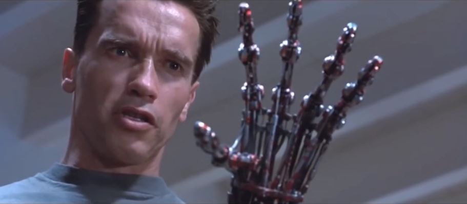
I had dreamed of building a Terminator T-800 arm ever since I saw this scene in Terminator 2 decades ago. If I was going to do it, I didn’t want to build a kit–I wanted to create the entire thing from scratch and as visually accurate as possible to allow it to still move, yet match the movie prop. The two were sometimes in conflict with other.

Having done a lot of resin work in the past, I considered machining the parts from machinable wax then casting in resin. Since there are no duplicate parts anywhere in the arm using castings wouldn’t be efficient. Casting is ideal for multiple parts that are identical so it seemed like overkill in this case.

I originally decided to approach the project as a buildup in styrene and resin. First I’d do a prototype of one phalanx (a finger bone) of the index finger of the hand. This would allow me to test the strength of the build and the epoxy & glues I’d be using.

I found someone on the internet that had access to the original Terminator props and precisely measured them, transferring it all into some precise drawings. In all there were nearly 60 pages of sketches.

I started the research and development for the project in October of 2012 and discovered a lot of information about the various props used in the Terminator movies. The actual choice of which arm I would build was a bit vaque until the research was completed. It took around 3 months to gather all my sources, learning what was incorrect information on the web and what was accurate.

I’ve broken the project blog into several categories based upon my attempted approaches and final builds. Hopefully it will prove entertaining if not educational. Several people have built arms since mine based upon discussions they have had with me that spurred them to their own projects. Children of the Arm, as it were.

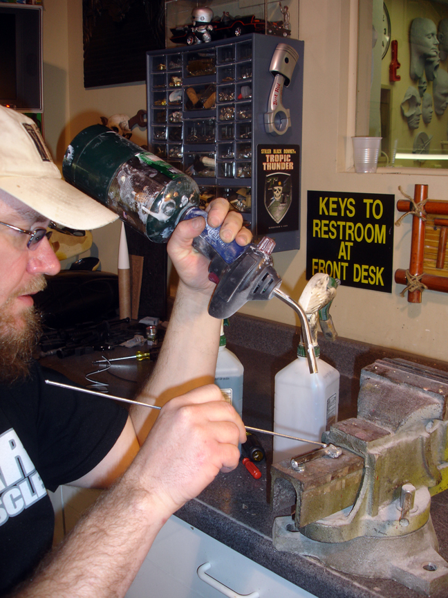
Most of the Shop projects on this blog are a result of the learning experience I spent on the T800 hand. Learning techniques, building my own tooling, restoring old metal tools that I could use. An expert metal worker could probable have done the hand in a week; I had to learn and build everything along the way. These distractions, while time consuming, helped me with the techniques I would need as I built the hand. I’m nothing if not very patient.

This shot from Terminator 2 revealed many differences from arm in the first Terminator film. This spurred me to serious research into the various props. Here is a summary of what I learned. The very nature of the web being that ‘everyone with a keyboard and opinion is an expert’ must be remembered, and I did my best to sift through to as many facts as seemed verifiable.

What I can tell is that there were several skeletons and/or arms made for each film so it will always be debatable as to ‘which was which”.

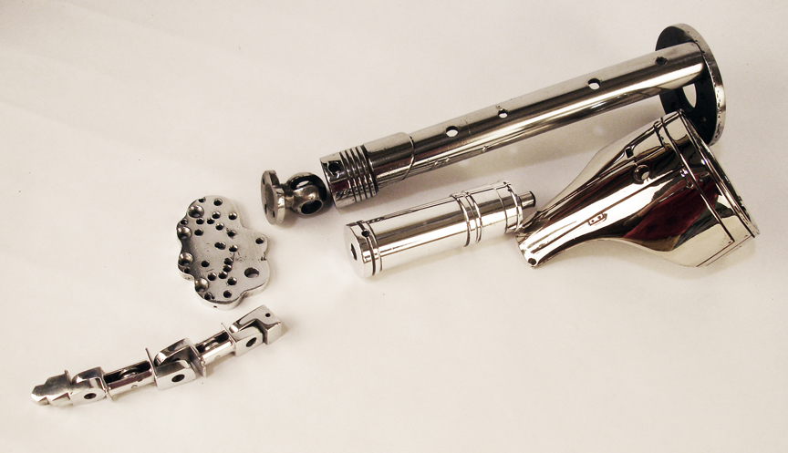
The original terminator arm was created for the first movie. For the most part this arm was made from what looks like steel and aluminum and many parts were ‘pressed’ or ‘bent’ into their final shapes. A few select pieces were cut from existing devices such as engine pistons.

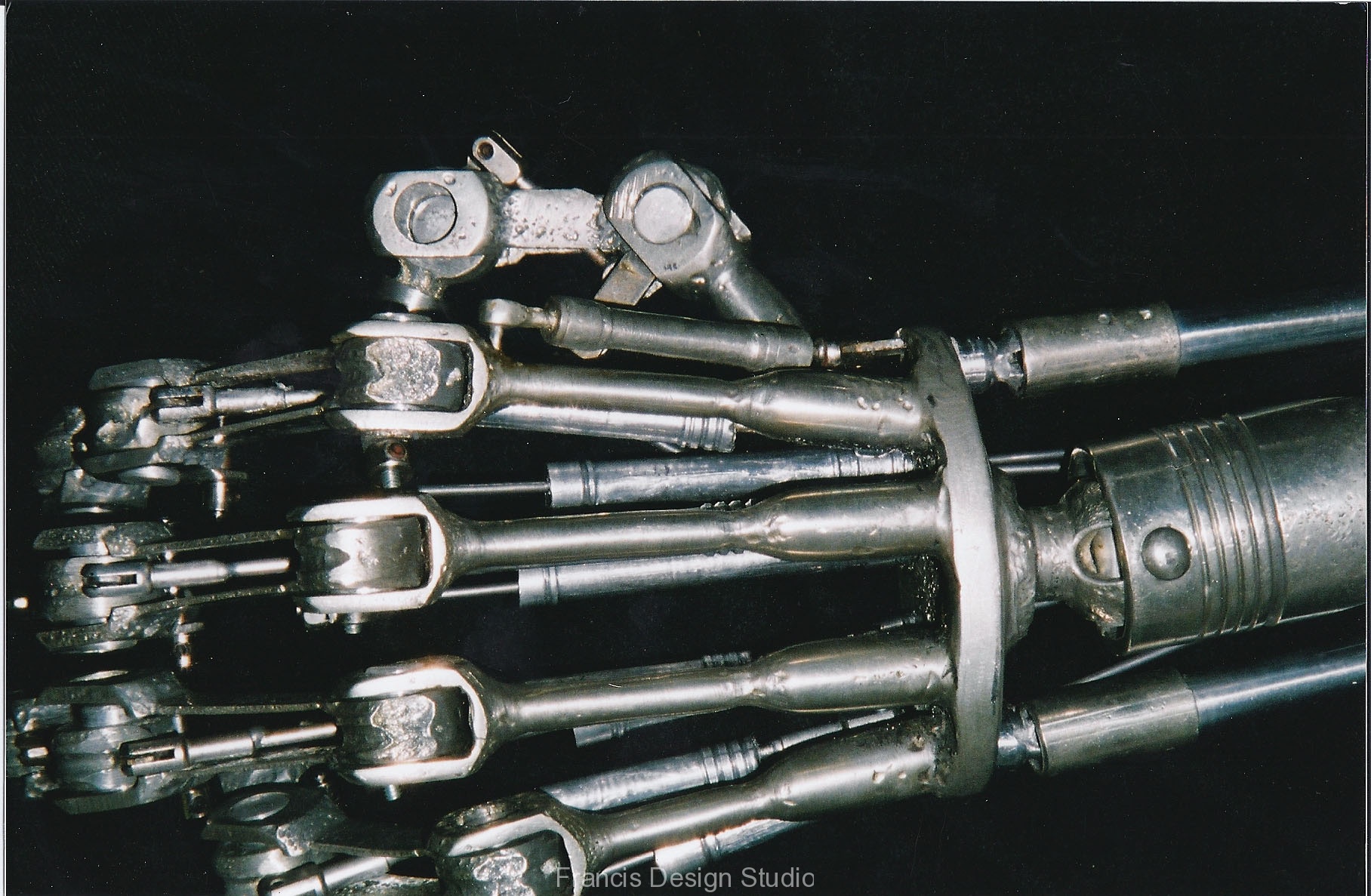
You can see much of the damage inflicted on the original props during shooting and afterwards. ‘Blobs’ where pieces were welded quickly in order to get through a scene are apparent in the knuckes that are now permanently fused together. The first film’s prop is much less detailed than that of the second film. Interestingly, the wrist joint and three forearm piston muscles are very similiar between films. According to sources, the original arm was not tripled chrome plated. Some parts where steel, and you can see many of the ‘smaller muscle pistions’ of the fingers were actually stainless steel control rods used in radio control model airplanes. Most of the steel parts have a reddish tint to them in these photos as they have begun to rust.

Once the Terminator 2 film began production, entirely new props were made. This arm was not triple-chrome plated either, and also contained a fair amount of aluminum. This prop was than vacuum metalized later.

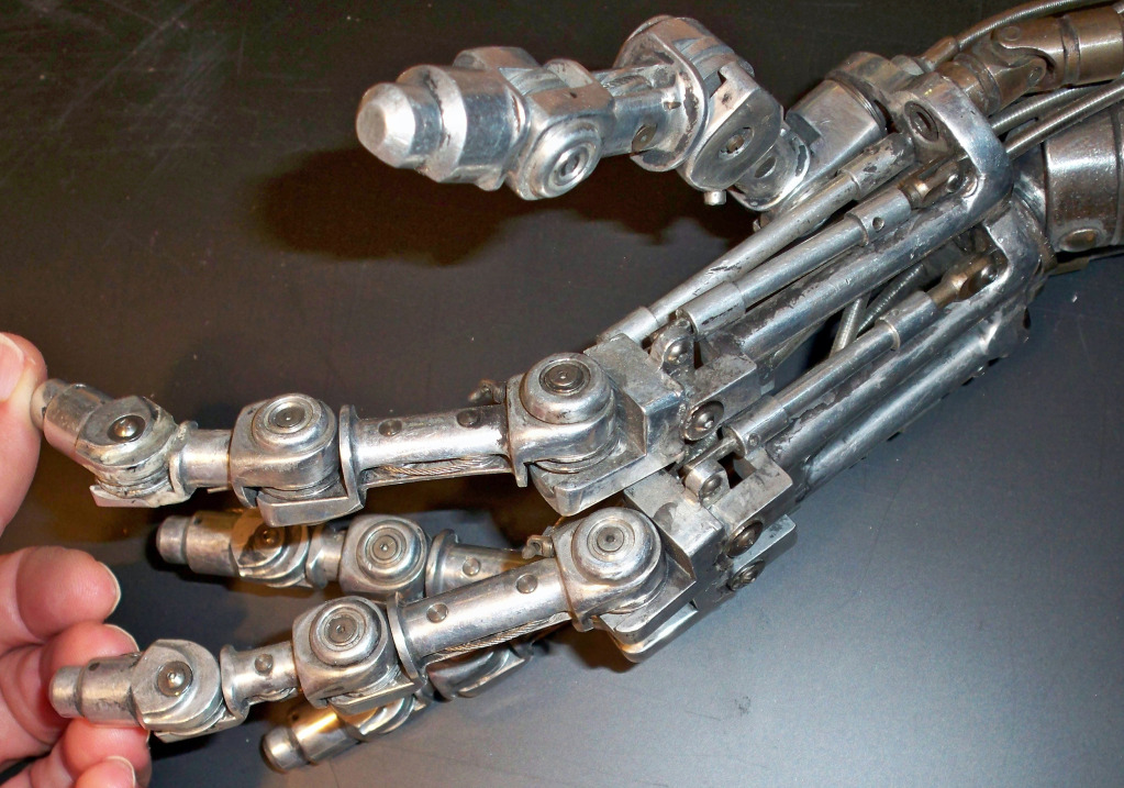
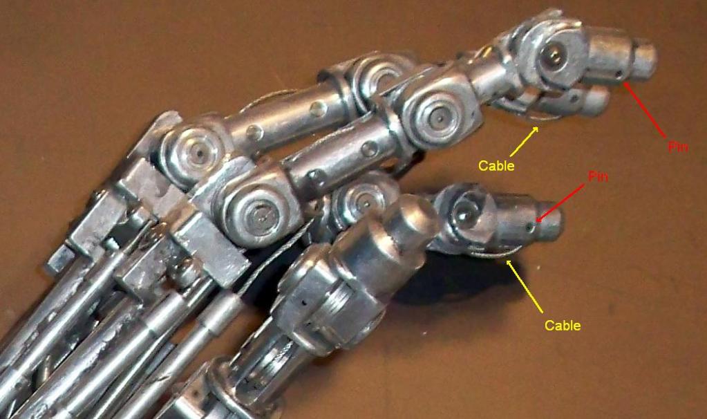
Much more detailed work went into the machining of the bones of this arm. There is also a lot of cabling through pistons and pulley, allowing some movement. Most of the axels consist of steel pins thread with stainless steel hex screws and custom made ‘washer caps’ on both sides of every joint.

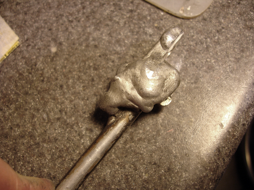
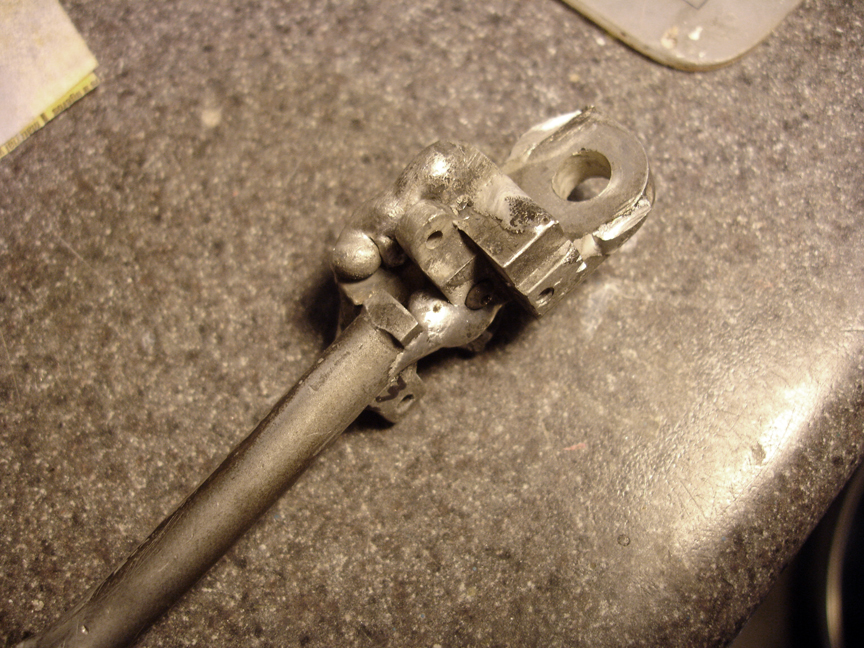
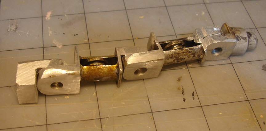
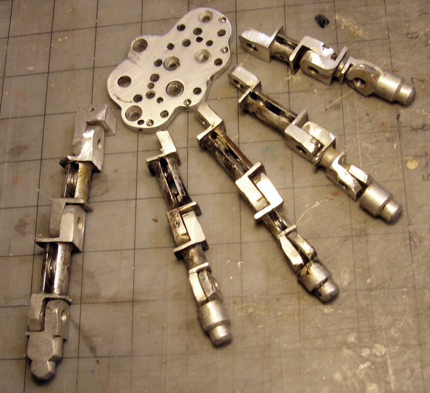
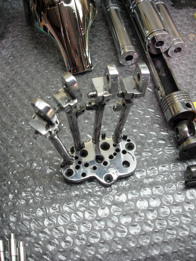
During shooting a LOT of damage was done to the props. This happens during a shoot, and no one thinks twice about damaging a prop in order to get the day’s shooting completed. So if a finger breaks, someone will weld it, solder it, glue it, whatever it takes to quickly get the shot completed. By the time production is completed, props hardly be recognizable from what they once were, as evident by these photos….brace yourself, these are painful to see…..

Ugh. It’s like looking at the results of mechanical arthritis.

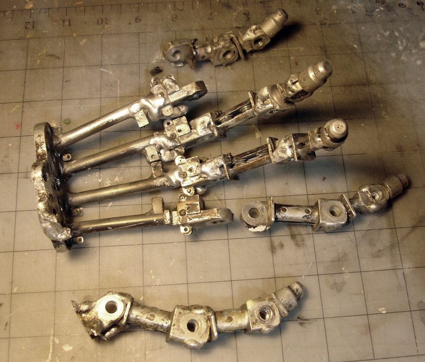
Not only is all motion now rendered impossible, some of the pieces can barely be identified. Aluminum melted by welds, giant blobs of melted metal or solder, and large pieces ground away. It get worse….

This is the palm plate of the hand, probably crushed in a vise during work.
This looks like it may have been a metacarpal bone. Somewhere under there is art.

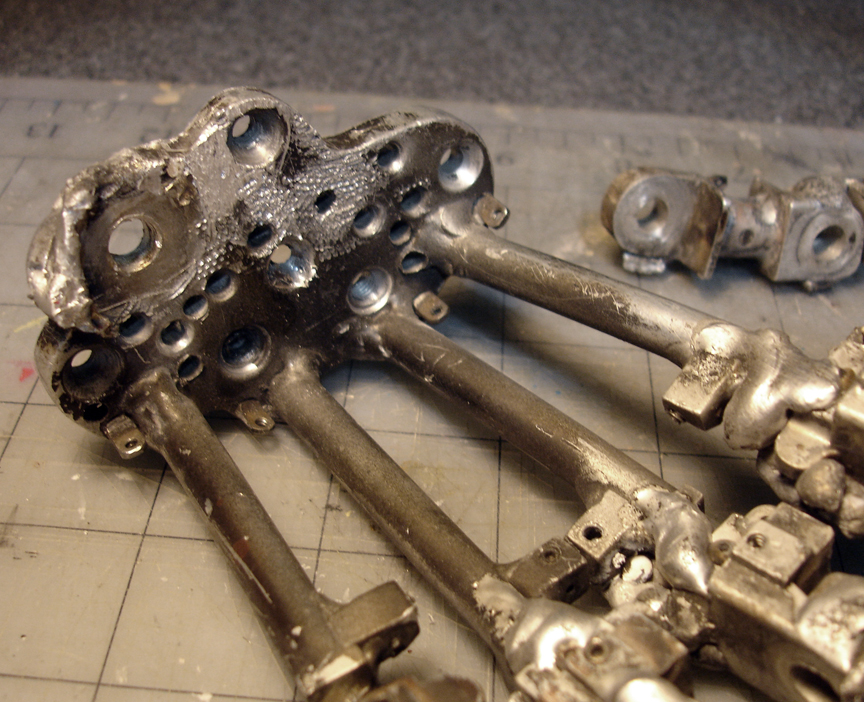
As near as I have been able to tell, after T2 finished filming, the endoarm was sold to a company called Profiles in History along with an endoskeleton that they cobbled together as a prop for the magician Chris Angel’s stage show. The endoskeleton was composed of replica and original parts including this once fully animatronic arm. By this time it was very damaged form the heavily welded, sodered and deformed parts. Much of the detail was lost.

At this point, Lucasfilm Limited was hired to restore the arm, possible for their part in the Terminator Amusement Park Ride, but this is unconfirmed.

I don’t know who he is, but he gave it his best shot.

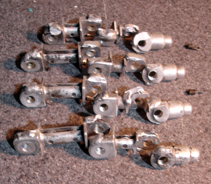
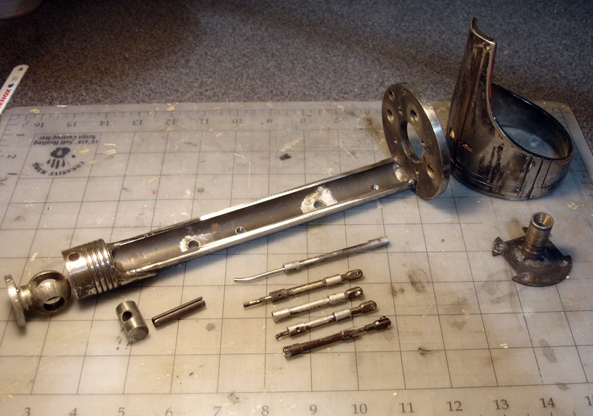
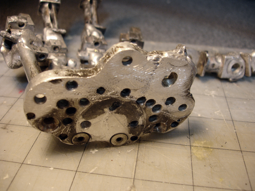
The arm was then broken down into individual components, cut apart and ground down in an attempt to restore detail. According to accounts, over 100 hours of grinding and sanding went into this. A lot of damage was done to the once sharp, details edges of the corners, as all later pictures show edges with a more ’rounded’ profile. This was probably unavoidable at this point. A lot of filing was also done into once filleted joint corners, and the entire thing was then smoothed (probably by tumbling in media).

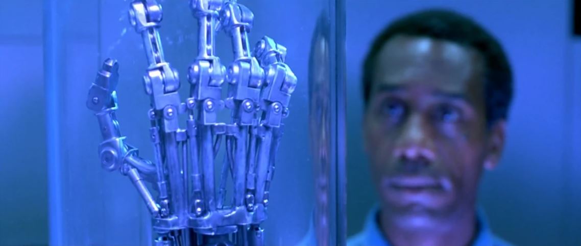
At this point the pieces were then chromed and reassembled.

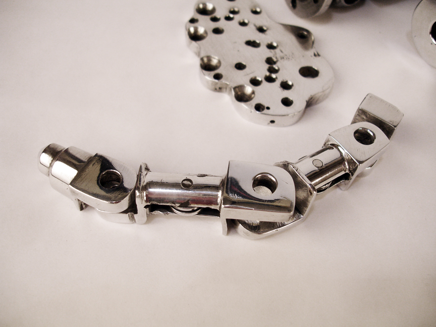
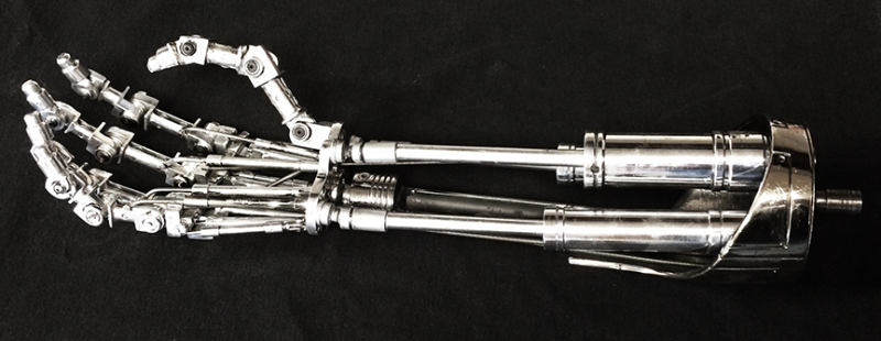
Although now quite silvery, the arm’s original glory is as close to it was before shooting as possible.

1-Project Origin and History

My original plan was to pilfer the two 36″ nylon parachutes from my never flown Sparrow rocket for recovery. However after feeling the weight of the new bird I’m starting to think I might need some beefier chutes. Also need to track down some heavy-duty shock cord to absorb the ejection charge.

One of the things that the original rocket had a problem with was that the nose would “bang” against the body during descent and do some surface damage to the fins and body tube. I could have the nose and body recover separately but I think some adjustments to the position of the chutes along the shock cord can cure this problem.

Have to work on recovery stuff a bit….also need to decide on launch guidance. This one is a little large for a standard rod/lug system so I’m looking into a rail-guide. Need to do a little more research on this.

Rocketry

Now that the four fins have had their bases epoxied to the engine core using the outer body as a guide I can remove the core and begin reinforcing the fins and interior.

I purchased some heavy duty fiberglass cloth for the reinforcing of the engine mount tubes, fins and centering rings where they all will bond together. For this I used pure epoxy (no thixatives or micro-balloons) so it could saturate the thick cloth and seep into the wood surfaces for a secure bond.

Thanks to my old friend gravity, I could only do one side per day. This prevented the epoxy from dripping down fins or running down the body. The US Composites Epoxy I use is extremely thin in it’s purest form giving it a good soaking bond but runs are quick to appear. Even though the pot life was 15 minutes I wanted to make sure there was no chance of runs. The pure epoxy is very hard to remove or sand.

Three layers of heavy 6 oz. fiberglass cloth/pure epoxy across each fin root/centering ring/engine tube. Then a wrap of one layer of 6 oz. cloth around the entire remaining length of the engine core tubes for some added strength. This should help distribute the engine thrust across more of the length of the main body tube.

A test fit of the finished engine core/fin unit into the slotted body tube showed that it all fit together. Whew!

Side-by-side of the last version with the current version ready for final assembly and final primer & sanding. The new baby is a little taller because of the difference between the old Estes-BT101 nose cone and the PML 3.9 Nose cone but this couldn’t be helped without turning my own nose cone. Since I don’t like lathes this’ll have to do. I did shorten the body a couple inches to help compensate but the added length will help compensate for the heavier tail due to added engine weight. Looks like the center of gravity will be darn close to the location of the original helping to maintain stability. A trip through the RockSim software helped confirm this theory.

Rocketry

It took another coat of primer, sanding with 220 grit then wet-sand/polishing with 600 grit paper to get the fins to a silky smooth surface. Now that I’ve completed the whole fiberglassing process for the fins I’m 95% satisfied with the results. I think the fiberglassing process gave me fantastic strength but the amount of labor to finish the outside of the fins and get a glassy-smooth surface just wasn’t worth it. Given another take, I’d triple up the heavy fiberglass on the interior of the fin between the perpendicular basswood layers but I’d skip the fiberglassing of the outside of the fins and go with multiple coats of sanding sealer. The pinholes and slight waves in the fiberglass surface just involved too much work to get a glassy finish.

First I scraped the root of the fin down to the wood and soaked the edge with pure epoxy to allow it to sink into the wood for a few minutes. After dry-fitting the engine core into the main body, I added cabosil thixative to the epoxy to keep it from running and applied it to the engine core fin location through the body slots. Now the fin could be inserted into the body slot without worrying about the engine core or fin being glued to the body. By not gluing the core or fins to the body I’ll be able to remove them and reinforce the fins and core later.

Second fin epoxied on (1 every eight hours, allowing time for the last fin to cure and not “drift”. Gravity is my enemy when gluing up. Pulled the engine core our to check that everything was still removable–didn’t want to find out it was too later after the fourth fin….then put it back in for the third and fourth fins.

Rocketry

Before slotting the main tube for the fins (which are mounted through the wall and onto the engine motor mounts) I though I’d try a test. I wanted to be sure that my jib saw wouldn’t vibrate the tube too severly and shatter or crack the spiral seams I had to painstakingly filled. Glad I did. The jigsaw shook the test tube enough to rattle out some of the filler. Now that I know I tried using my Dremel with a cut-off wheel. Takes a bit longer because of the impregnated phenolic for it was worth it to avoid damaging all the labor I’d put into the seam filling. Cutting phenolic tubing is more like cutting oak than paper.

Now the tube has been slotted to the fins. After they’re completed I’ll do a dry bit of everything. A compressor comes in very handy for eliminating dust after sanding….just remember the goggles and respirator when blowing all that phenolic and fiberglass dust about.

Rocketry

Although I learned a lot about fiberglassing by using it on these fins I’m not sure I’d do it again. Although the added strength is wonderful the work that I went through finishing the outsides doesn’t seem worth it. Too many air bubbles or waves to fill. Not sure how to reduce that and still get a perfectly flat surface. I think next time I would increase the number of fiberglass/epoxy layers within the fin’s layers, then stick with sanding sealer on the outside of the plywood. Here’s a few more shots of spot filling the surface of the fins and primer, gradually getting the smooth surface I wanted.

After one last coat of primer I’ll hit them with some wet sanding at 600 grit to prep them for final paint.

Rocketry

Filling in the PML phenolic body tube spirals is definitely the most tedious part of this project. Three successive passes each of filling, sanding, priming to get them nearly seamless. I say “nearly” because I can still see them if the light is at the right angle. I will definitely try Quantum tubing next project if for no other reason than to avoid this labor-intensive process.

Pics of each pass getting gradually smoother. Also more squadron putty for pass two on the seams and injection points on the nose cone….

Rocketry

The PML 16″ nose cone arrived with quite a few flaws–seams, grooves, injection dimples…and a ding from a surprise driveway bounce.  Time to break out the squadron white putty and go to work. That stuff dries (too) fast so you need to work quick. It also dries harder than stone which makes sanding into a workout.

Rocketry

Now that the fins have fully cured I cut them down to size with a jigsaw and a fine plywood blade. Because of the fiberglassing I wore goggles and a respirator. It’s tough to work when your covered from head to toe but it beats getting fiberglass dust in your lungs and eyes. That stuff makes drywall dust look course by comparison. It gets into EVERYTHING. I keep my shopvac pointed at the saw blade while I cut to minimize floating material in my shop.

I half-rounded the leading edges and squared off the trailing, root and outer edges with a sanding block with progressively finer grains. I then brushed a thin pure epoxy coat onto the freshly cut leading, trailing and outer edges and allowed it to soak into the raw wood before sanding. This will seal the outer edges. I won’t do the root edge until the fins are mounted so that the raw epoxy will soak into the wood for a better bond.

The fiberglass and resin made the fins very tough and difficult to sand. I’d like to try a stress test sometime with some scrap to be sure but I’d guess offhand that the fins are at least 5-8 times stronger than bare wood.

The last Cobra’s fins were epoxied onto the outer body tube. This model’s body tube will be slit to allow the fins to be mounted “through-the-wall”. They will be fiberglassed directly onto the motor core. The notches in the fins allow them to mount over the motor mount’s 1/4″ plywood centering rings within the body.

The fresh-but edges of the fins clearly shows the glass-wood-glass-wood-glass layers. It’s a heck of a lot more work than the old balsa fin days!

Rocketry

After sanding the filler, two coats of primer and sanding again the spiral grooves were better but still visible. Time for another coat of filler. This is a very tedious process that reminds me of rotoscoping. I can do about one inch per minute so a four-foot, four inch diameter body tube takes a while. Time to turn up some tunes and get in the zone.

Rocketry

I don’t think we ever even though of filling the grooves in body tubes when we were kids but nowadays it’s standard operating procedure for a good finish. The main body four-inch phenolic tube has spiral grooves in it you could drive a truck through.

Filling them with a 4:1 mix of Elmer’s Carpenter Wood Filler and water works well. VERY tedious to fill these with a stick, then sanding them down lightly, repeating the whole process two to three times. Lots of dust, too.

Now it awaits some primer to really show off the flaws.

Rocketry

Having settled on a six-engine cluster configuration I began building the engine core. I was also planning on the fins being mounted “through-the-wall” and directly into the core itself. This created a nice little puzzle for planning what could be built & glued first.

I started with the core “short”–that is, just past the length of the engines themselves–so I could work from both sides mounting higher power engine blocks. Later I would mount the ejection charge extensions and fins before mounting the completed core into the main body. The inner seventh engine tube is just a space-holder to keep the outer six in place while the epoxy cures–then it can be removed.

After cutting some 1/4 five-ply centering rings and dry-fitting everything I epoxied the core together. I used expended D-Engine slices as heavy duty engine blocks in addition to engine hooks to hold the engines locked in during ejection. Then a second pass of epoxy fillets thickened with Cabosil to keep it from running. After the fins are finished and epoxied to the engine core I will add heavy fiberglass and epoxy to strengthen the whole core mount.

Here’s the completed motor mounts awaiting fiberglassing for added strength when the fins are mounted to it. Can’t wait to see this puppy loaded with six E30s!

Rocketry

During curing the surface epoxy developed two problems: Irregular surface dent from large bubbles between the epoxy and wax-paper protection layers, and micro-bubble pinholes from the plywood and fiberglass cloth degassing. Here they are highlighted because they are full of fiberglass dust after a light sanding.

I’d encountered degassing resin problems before while building my Arc Reactor prop and new that there was only so much you could cure with higher temperature epoxies and curing. Since this surface was to be painted I would deal with it post-cure.

I experimented with Cabosil-Aerosil thixatives and epoxy but found that an epoxy-based filler was far too hard to be able to sand down without damaging the existing epoxy finish down to the fiberglass cloth. I guess this is why we test on scraps.

I’d planned on using Elmer’s Carpenter Wood Filler as a patch for the body tubes and thought I’d give it a try here.

Worked great! Takes two or three passes of filling with a popsicle stick and sanding with very fine sandpaper. A mix of 3 parts Filler with 1 part water softens the filler enough to “flow” into the finer bubbles….but they do have to be filled individually. Too much filler on the larger surface means more sanding and that means risking sanding down to the fiberglass cloth and ruining the fin.

Rocketry

My original cobras were tested the old-fashioned ways: you measured for center of gravity and center of pressure then “flew” the rocket at the end of a rope around you like a sling to test it’s stability before flight. THEN you launched and hoped you got it all right. Well now we have simulation software that lets you build and test your rocket before you even hit the hobby shop for parts. RockSim is a really nice simulation program and I used it to flesh out my designs.

Once I proofed my new design and had some simulation data to work with I settled on an engine configuration that could handle six D12s, six E9s or six E30s. I could probably jam in six F60s but that might be pushing it’s stability because of the extra engine length. Besides, big fields are harder to find now than when I was twelve years old.

First, fins. Although it worked well for my original Cobras, old-time Balsa wood is out of the question for this size. Some type of enhance composite was required. I had never done epoxy-base composites before so though I’d give it a try. New techniques keep my interest better. I experimented with carbon fiber, kevlar and fiberglass a bit to test some ideas. In the end, fiberglass was the most cost effective method and more than strong enough for this thrust class. Carbon or kevlar would be necessary if I get into the H engine and higher classes. Besides, they cost 4-10 times as much as fiberglass.

After doing some strength testing for a few weeks I settled on a five-layer plywood & fiberglass composite fin. By laying out the plywood layers with their grain perpendicular to each other I was able to increase the strength of the fin many times before even introducing the fiberglass layers.

I sandwiched a layer of heavy fiberglass cloth in epoxy between the two perpendicular grained, 1/8″ three-ply plywood bases.

This gave a very strong core for the fins.

Now for the outside. I layers a medium density fiberglass cloth in an epoxy soup with Q-Cells to make the layer softer to finish. Not enough to lose structural density–just enough to make the outside easier to finish sand. I sandwiched all the layers between two marble floor tiles–the smoothest, least likely to bend material I could find–and weighted them for 48 hours to cure fully.

Lost a test set because I didn’t realize that the epoxy lubricated the layers enough for them to slide out of alignment during the night even with weight on them. Learned a lesson–lock everything down tight!

The finished product is a lightweight, incredibly strong fin. But the finish left a bit to be desired.

Rocketry

In 2011 I got the itch to fly again. I’m hoping to get my nephews out next spring for some flying so I decided to revisit the Cobra design. I think she’s still in my storage room…..

Well, she’s a little dusty and has plenty of dings (character!) and cobwebs but is still flyable.

OR…. I could build a better one with more power!

….Time to experiment with some newer building techniques first.

Rocketry

I think I launched my first model rockets when I was around eight or nine years old at the local school fields. I remember my younger sister molly riding in my wagon as we hauled it and my fleet out for flight. She would chase them down as fast as I could launch them. When my other sister and brother were old enough they would accompany us as well. The early fleet was half store bought and half homebrew.

Polaroid! Those who remember Estes might recognize the SkyDart, Atlantis, Condor (sans Glider), Andromeda, Orbital Transport, Interceptor, Photon Disruptor, Mini-Saturn V, Mini-Beta (that was my little brother’s) X-Wing and Mercury Redstone. Also a homemade 110 Titan IIIc camera rocket I had worked up with Tony Campana, another bud. This was the fleet in January 1976. I took a lot of flack for painting the Photon with house paint. Hey, it was cheap and handy!

In Junior High I met Mike Aprile, Brian Hebel and Paul Candel with whom I would launch a lot of rockets. Between the three of us we flew anything Estes or Centuri made. Heilmann Park in Detroit was our field and the trees around that park probably still contain many of our birds that never made it back into our hands!

I entered the state competitions a few time back then and snagged a few ribbons. My dad would drive me to Ford Field for state matches and to watch the R/C Airplane competitions. He drove me around a lot for those things and always pushed me to enter those and join rocketry clubs and such and because of him I learned a lot.

I first saw the Cobra M1 missile in 6th grade in a military book. It was a four-inch diamter, four foot long anti-tank missle. I decided to build one in 1980 that was full-size, the actual size of the real thing. It used a D12 engine and gave a nice, slow, low flight at the state meet that year. I was mighty proud of it. This design became a foundation for me when trying new build techniques in the following years.

The same year one of the advanced rocketeers introduced me to medium/high powered rocketry…..WHAT? You mean there are engines bigger than an Estes D?! I’d never heard of such a thing! I was an E flight that year, and F and a G engine! I was stunned by the power of those things! The next year, I refitted my Cobra for an F100 and flew it at the state meet. However, I wasn’t prepared for the thrust the F100 could put out and it ripped the guts out of the Cobra. That was when I learned that Elmer’s Glue and Balsa were not up to the task.

In 1985 I built a new cobra using a three-D12 cluster (F100 engines were expensive!) and got several excellent flights. It was a good crowd-pleaser because it made lots of noise and flew slow enough to watch the exhaust. On it’s last flight I had a an engine core blowout and the remaining engines couldn’t eject the parachutes. After a nose dive from 900 feet she smacked the ground hard enough to wake the prairie dogs.

“What the heck went wrong?”

After repairs and a fresh coat of black paint she flew several more times before retiring to storage.

Rocketry

Around 1987 I was into my home audio/video system big-time. Between surround, cassette, open-reel, mixers and synthesizers I spent more time wiring than I did using the gear itself. I thought it would be fun to build a matrix router for all my gear. My buddy Dieter, who taught me a lot about analog electronics, had helped me design and build a 16 channel mixing board already so I thought I would tackle this one on my own.

My intended feature list was:

-16×16 matrix of four-channel audio, single channel composite video

-Capability to breakaway any channel

-Touch switch user interface (touch switches were so new and cool back then!)

-Serial interface for computer control

I broke the project up into several boards that were then plugged into a motherboard bus that was contained in a 19″ rackmount case. I’m not sure what became of the front panel/user interface I originally built….that was a few years ago.

The middle board (pictured) was one of two boards that with custom touch-switch circuitry to handle a keyboard of small metal plates arranged as a phone-type keyboard. You typed “Source” “2” “Destination” “5” and that would send input #2 into output #5. This typing was interpreted by the leftmost board (pictured) into a parallel array of data that was used to control the rightmost board–one of several boards that handled the A/V matrix switching. Note the missing chips that were scavenged for later projects!

It worked. A little piezo returned a “click” sound as you touched the metal button/plates giving it a nice “aural feel”. Video quality was weak because analog video circuitry wasn’t my strong point. Audio worked well although bandwidth was weak because of the switching chips I used. I learned a lot about analog circuitry on this. I didn’t take it much further than a few ins and outs….once I realized that the quality wasn’t there it was hard to stay interested.

AV Router

Back around 1983 I was experimenting with Voice Synthesis in software on a Commodore 64, recording phonemes and playing them back. At the health club I worked in I met a gentleman who was a saleman for the Detroit-based Votrax company that created the SC-01 Voice Synthesizer chip. When he heard I was an electronic hobbyist he graciously gave me an SC-01 chip (which retailed for several hundred dollars as I recall).

I went right to work building a small amplifier/buffering board for this puppy so I could plug it into the parallel port of my C64. I still remember how cool it was to piece together human-sounding voice from that little chip!

Voice Synthesizer

This one is a bit of a mess, having been scavenged for parts over the years. Originally I built this as a successor to my first 3D digitizing device back in 1990. Unlike the manual method of digitizing that the first model used this was intended to be fully automatic–place an object in range and the digitizer would repeated search out the object until it had enough data to display the wireframe. It used several stepper motors to position various contact pointers until it found the surface of the object and found data. It worked–sometimes. It was only functional on shapes that could be “lathed” or were symmetric around a center axis. I built it as more of an excuse to learn to use stepper motors than anything else and I succeeded with that goal.

DigiPen 2

Back in 1988 while using Sculpt-3D on the Amiga I wondered if I could digitize 3D objects with a custom hardware device. I constructed this little monster, the DigiPen using hiresolution potentiometers and an analog to digital converter. There were originally four joints in the arm of the pen (I’ve since scavenged some for parts on other projects). You held the pen in your hand and touched the object being digitized. It could “trace” an object in real time into a 3D model using bezier curves or polygons. I used the pots and built a multiplexer to allow me to use only one A/D because I couldn’t afford to have four A/D converters….and pots were a lot cheaper than optical encoders at the time. I learned a lot about multiplexing hardware with this project as well as serial communications and matrix mathematics for 3D.

It worked amazingly well. Originally it had a standalone user interface that I wrote for the Amiga. Later I interfaced it into “Vertex”, the 3D modeling application that I wrote whose source code was subsequently stolen.

Today there are several devices available commercially that perform the same task in higher resolutions.

DigiPen 1

I’ve always been disappointed with the lack of a decent desktop user interface for media management in visual effects software. Only Discreet/Autodesk’s Flame software has ever come close to perfection when it came to managing media, although it has stagnated over recent years with lack of true innovation.

I undertook the task of creating a “desktop environment” for media management with the single goal of proving to myself that I could do it. My FXDesktop was that application. Since it was merely a proof of concept I didn’t make it very robust–but it also taught me a lot about media management in the process.

Unlimited libraries, desktops, clips, reels, frames of multiple file formats, scrollable clips and reels, lots of fun trying to duplicate the Flame’s user experience. I designed it as a dotnet component, making it drag & drop-able into any dotnet application.

As a side-effect, I also now had a nice clip-viewing component that I have used in several other applications.

I never had any intention of taking it to market or implementing it in real world use. I basically tried to duplicate the functionality of the Flame desktop and I give all credit for the original design to the kids at Discreet that wrote the original implementation.

FXDesktop

While writing the firmware for the circuitry in my SubSpace Pod, I learned to dislike the Inegrated Developer Environment, or IDE for the Parallax Basic Stamp. The Stamp seemed to have a large following but very little third-party support for programmers. I thought perhaps I could write a better IDE for their line of programmable microcontroller chips and possibly market it. It would involve writing some very complex code and low-level drivers for programming the microcontrollers (all seven of them) and would also give me an excuse to learn to build web sites.

The toughest thing was writing the low-level communications between my application and the stamp’s microcontrollers. This took about a month. Lots of critical timing involved in those little buggers and their serial interfaces. I built some hardware so that I could program and test five different basic stamps at the same time via the IDE.

This made troubleshooting the code much easier. I based the IDE (which I called IDEa) on a multiple-document interface. It allowed dockable windows, customizable user layouts, a complete solution/project manager that added the ability to create header/#include files, multiple source files, syntax highlighting & code folding, inline syntax help, code snippets, intellisense code, bookmarking, progamming multiple stamps at once. None of these features was available to basic stamp programmers until this point.

It worked great. Fast, full featured and far more user-friendly than the default IDE included with the Stamps. This is one of my cleanest pieces of code and I’m mighty proud of it.

IDEa for Basic Stamps

While at GTN our 3D/CGI department began to encounter a need to digitize cars and trucks for computer modeling. Like most things in our business, the first mention of something is usually within days of actually needing it. We quickly reviewed a couple of digitizing arms and scanners that were available but nothing had software that was optimized for the work we do. A couple of my coworkers suggested an application that they had used previously but it appeared that the software (originally called Hyperspace) was no longer produced and we were unable to contact the author. We discussed with a commercial developer having a custom plugin written to allow digitizing in Autodesk Maya but the cost was outrageous, and I frankly thought it would be more limiting to have the application dedicated to the Maya infrastructure.

I had designed and built two types of contact-based digitizing arms about 15 years previously; a project I had intended to market but lost interest in when confronted with the high costs of patenting and copyrighting. My interest in digitizing was reignited with our need for an optimized application for digitizing and I began to visualize how I would write such an application.

My coworkers and I discussed the basic needs on a Friday and I whipped together a prototype of the application over the weekend. Within two weeks we had a functional application and began adding features. SubSpace had been born and would evolve over the next few years as we did more and more digitizing jobs around the world.

SubSpace was written in VB.Net. Like all my current applications uses my SkeletonFramework plus some custom 3D code from a 3D Modeler I had written in 1991 called Vertex for the Amiga platform. I continued developing SubSpace steadily on my own for several years and continue to maintain it.

I recently refactored the entire program to neaten it up a bit and upgrade it to the newest OpenGL libraries for Windows. I quadrupled the speed of the application and added a bunch of new features in this, version 7.x. I’m really proud of how this program turned out and have yet to see anything even close to this efficient.


SubSpaceAll


The main UI consists of a Tools form that permits access to all main functions, and access to secondary forms with other functions. Bookmarks let you jump quickly between saved models or parts being digitized. Multiple Views let you see the parts being digitized from stored camera angles. A History form records everything you do for unlimited undo/redo capabilities. Stored Layouts let you configure the screen layout of the windows and recall those settings at any time. Presets allow customization of the buttons and keys of the digitizer and keyboard. The viewer is (with v7.x) a full OpenGL viewer and displayed the work being digitize with options for fog (helpful when trying to view distances) and simple lighting.


ToolBar


The main ToolForm with all it’s functions.


Main


The OpenGL Viewer. Text information is now full configurable and has drop shadows!


Prefs

Every app I write has tons of preferences so the user can customize everything to his or her needs. These are stored and can be quickly swapped with other prefs settings.


While using our digitizing arms (two Faro models) I thought it might be nice to have some type of wireless control of SubSpace for myself–rather than having to reach over to a laptop for control. I came up with an idea for a SubSpace Pod (or Pendant), a wireless controller for the application. I’d never done built or programmed any wireless hardware like this so I was immediately intrigued by the challenge.

I prototyped the whole thing using a Parallax Basic Stamp, some Bluetooth wireless circuitry, a twenty key matrix keyboard and a small LCD screen for feedback. I wrote the basic stamp code/firmware and created a two-way link between the SubSpace application on the laptop and the Pod. This allowed the LCD screen to display lots of useful info as well as allow user-feedback of selected function on the keyboard all without having to touch the laptop.

In the end, I rewired and miniaturized the whole thing into into a 4×5″ case and got the power requirements down to 9 volts–enough to make it portable and light. It works really well and was one of my favorite hardware projects.

SubSpace

Miranda is a Render Controller Suite that I wrote. It began life when I worked at Traveling Pictures around 1999. We had the beginnings of a render farm, as series of computers designed to “divide and conquer” large computer graphics projects and were attempting some of the first photoreal 3D/CG cars. We used Houdini and Lightwave for our 3D work at the time and the render controllers at the time were either too limited or too expensive.

Having written a lot of code over the years I took it upon myself to write a render controller in my spare time. Since it was mainly for the Houdini renderer I called it “Harry”. Harry used a simple watch folder system for frames at first–anything placed into a folder named “waiting to render” would render. As I spent more and time on it, it evolved into a more capable system with priority/precedence based queues. About a year later we began utilize renderers other than Houdini’s so I changed the name of the system to “Miranda”.

What makes Miranda different from the other render controllers (there are about 12 out there as of this writing) is that it is designed with an overview of all jobs in the system at once. All other render controllers are “job-centric”–meaning that they can show you lots of info on any single job. Miranda show the status of every frame in every job all at once (provided you have enough screen real estate) giving you an overview of the entire facility. Miranda manages up to 400 machines and about 100 jobs very well–she was designed to give maximum control to multiple people in a medium-sized facility and works very well. It’s interface, a Timeline showing every job and frame in those jobs is still unique among the field. It is my longest running personal project and remain in constant use on two render farms at RingSide Creative and is always under continuous review for new features.

Miranda

The Uncanny Valley is the effect described in 1978 by the Japanese roboticist Masahiro Mori. He noticed that the more humanlike his robots became, the more people were attracted to them but only up to a certain point–if a robot became too realistic but not perfect, people were repelled and disgusted.

This principle is also applied to computer graphics with regards to photorealistic humans created for movies. I’ve taken this one step further and applied it to actual actors and actresses as many of them have regressed backwards from reality into the uncanny valley.

An interesting thing about the Uncanny Valley as it relates to computer graphics–it seems as though nothing that falls within the valley is necessarily any better than anthing else in the valley–as though all uncanny-ness is created equal. Stated another way, imagery is either Uncanny Valley or Not–this is no percentage scale to it’s uncanny-ness. Imagery gradually gets better and better, then falls into valley or is perfect.

To be clear about this–I have no problem with someone attempting to create 100% photoreal humans–my problem is in claiming & marketing that you succeeded when it is obvious you failed.

Let’s start with the who’s who of characters that were claimed to be “100% photoreal CGI” that was destined to end the use of real actors:

Final Fantasy. We’ll ignore the boring plot and stick to the imagery…this stuff looked more like a video game that photoreal. I consider it over marketed to say the least but barely Uncanny Valley material.

Orville Redenbacher commercial. Even people who didn’t know that Orville was dead knew something was wrong with this imagery.

The Matrix.  Let’s face it–the effects were really cool, but the only reason most of the CGI people work is because they’re so motion blurred that you don’t get to look at them. Anytime they stop long enough to look at, the valley captures them cold.

Polar Express. The Valley personified. So much massaging of motion capture that it screams Valley. The characters appears to be continuously melting and morphing from on frame to another. A nightmare of souless children and floppy motion physics.

Beowulf. Into the uncanny valley of the shadow of death we go.

Image Metrics Project Emily. Plastic skin and a mouth that has a life of it’s own. Sorry, placing color bars between cuts doesn’t fool you into thinking it was shot live. Besides, the technique was technically “rotoscoping” since the CGI was “traced” off of an existing actress–and it still echoes in the valley.

Tron: Legacy. The young Jeff Bridges CGI character named Clu. Lots of dark, high contract attempts to hide it, but a visit to the valley nonetheless. He ain’t right.

Video Games. Every video game made in the last ten years has two parts: The part they show for 99% of commercials and ads (showing great graphics that are rendered in non-real time by major facilities as mini-movies and not really part of the game itself) and the actual game itself, which is always of lower quality because it utilizes the realtime renderers available to the hardware platform of the game. And the best of either lives in the pit of the valley.

Any woman who has ever appeared in a reality show about “Housewives”, “Cougars”, etc. These CGI facsimiles of real women look odd because of the strange facial proportions. Normal humans just don’t move or look like this. The motion seems stiff and the facial geometry is pretty distorted or paralyzed as though the muscles are broken. At least, I’m pretty sure that these women are computer generated. They sure look like they were created in the uncanny valley of CGI. I think.

Uncanny Valley comparisons

I decided to create a stand for the whole thing by using my existing silicone ring mold and more urethane plastic resin but in a candy apple red/black to match the Iron Man armor. This combined with a bronze nameplate and a soft resting plate allows the arc reactor to remain removable for close examination or in the stand without scratching anything.

A power plug that matches the movie prop and we’re done!

About two month’s spare time went into it and I’m very happy with the final result.

When the lights are on it’s so bright that it’s hard to look at directly (perfect!).

Arc Reactor

I built each “layer” of the reactor so that each could be built independently of each other in case I made design changes along the way, and I was glad I did so.

I had planned on adding an inner ring of light to the interior of the reactor using an LED ring light used in car taillights. When I bought one it wasn’t as bright as I’d hoped to I scratched the idea. I decided to place eight more high-intensity LEDs behind the repulsor emitter in a 1/4″ area of space.

Here’s a pic of the layers disassembled and assembled:

The layers consist of:

The main ring, the repulsor shielding, the main power cabling, the repulsor emitter, the repulsor reflector, the light chandelier, the secondary lighting ring, the repulser emitter light, the electronics layer, the mechanical layer (gear) and the heat sink foundation.

Here everything is stacked together and some of the heat sink fins are removed.

An inner lighting test….neat!

Here it is with all parts assembled:

Arc Reactor

I found some nice thin brass stock and brass wire for the transformer exterior wiring. I had intended to solder the fittings together but then realized that the plastic transformers would melt from the nearby heat. Time to make simulated solder!

After bending the brass wire to the correct shapes and sizes and cutting small brass mounting plates, I glued everything into place with medium-viscosity CA glue and CA accelerator. This causes the CA to cure before it levels too much and gives it a more “blobby” appearance. I augmented this appearance by moving the wires slightly as it cured to look more like manually soldered shaped. After all, Tony Stark built his in a cave from a box of scraps….it shouldn’t look too perfect.

A little solder-colored paint on each blob and the illusion is complete. I was very happy with this look.

Arc Reactor

Winding the transformers was one of the more difficult tasks on the project. I experimented with painting fake surface to simulate wire windings and several other methods but I couldn’t come up with anything that looked as well as actual magnet wire. That meant manually winding the 10 transformers by hand since the ring was a single piece. Cutting the ring wasn’t an option although that would have made winding the transformers a heck of a lot easier. The process took about eight hours total spread over a few evenings.

It takes three complete windings of the 30 gauge magnet wire to completely cover the transformer and get the proper “rounded” look at the edges. The black cores you see are vinyl to block any light from leaking through the windings and spoiling the illusion of transformer thickness.

I would start by winding approximately 40 feet of magnet wire onto a small custom “spool” that I made. Then I could pass the spool around and through the ring the hundreds of times it took to wind each transformer.

Although magnet wire this thin can be stretched I was unable to do so because it would actually distort the resin ring if taxed too much! A lot of patience went into winding these buggers and trying to get the wires as straight as possible.

You can now see the little “fake screw” details on the transformer sides highlighted by the polished chrome paint–Floquil chome paint is nice stuff that take a light polishing very well.

Arc Reactor

Originally I planned to have the arc reactor be just the ring itself in thickness so it could be worn under a shirt. Like most of my projects it evolved into the complete prop including it’s base. The base as it appears in the movie looks very much like a heat sink (given some creative liberties). This added a few inches of thickness to it but also gave it more accuracy.

I started by trying to carve the heat sink “fins” (of which there are twenty total of two types) of styrene–my medium of choice. They turned out to be too thick for that approach so I went with plan B.

I carved a prototype from thin styrene, then “traced” that onto a rolled piece of Sculpy clay of appropriate thickness. I then baked this in the oven for hardness, finished it with files and coated it with a sealer so it couldn’t absorb moisture. This gave me a prototype fin (two different prototypes, one for each fin type actually).

Then I built a mold box to accomodate the Sculpy prototype and cast a negative mold in my old friend, Smooth-on Oomoo silicone rubber after spraying it with lots of mold release.

I did this one using a two-piece mold technique: I poured liquid silicone into the mold box while empty to the half-way point and let it level and cure for 90 minutes. This gave me a flat base thanks to our friend gravity. I then sprayed it with more mold release and place the sculpy heat sink fin prototype flat onto the silicone base. I then poured more silicone onto the fin to the top and let that cure. After 90 minutes this gave me a nice two-part mold in which one half contains the actual part. This has the benefit of keeping the “flash” caused by resin leaks at the very edge of the part and makes it easier to finish.

For the resin itself, I used Smooth-On’s “liquid plastic”, called Smooth-Cast 300. This stuff is fantastic! It’s very important to get the ratios precise–the tiniest amount off and your castings are too flexible and mushy. Even though the measurements are by volume, you need to be very precise about it–no eyeballing! The resulting urethane plastice is hard enough to be finished like plastic but it is difficult to get paint to stick to it. Washing it with a degreaser (I use Simple-Green) and a resin-prep compound it critical and it helps to rough it up a bit with 1000 grit we sandpaper before a base coat.

Because I made a creative change to the shape of the fins I had to start over, but it was worth it. The new shape I have for the fins utilizes them to actually hold the internal parts, eliminating several brackets that I was going to create. Now the fins become actual structure parts of the arc reactor.

Here’s the finished 20 cast heat sink fins of the final shape. The first two have been glued to their base….

They are so closely aligned that I had to create a jig to mount them properly after painting–I knew I’d never be able to get paint between them if I waited until after mounting.

The completed Heat Sink foundation:

Arc Reactor

My original plan was the mount ten high intensity LEDs underneath the transformers. By lighting the ring from these hidden sources I thought I could hide the actual lights and cause the ring to appear to glow on it’s own. However, I cornered my self when I began to plan how to wrap the transformers with magnet wire. I found that I couldn’t wrap the transformers until after the LEDs were mounted, but I could mount the LEDs and run the wiring until after the transformers were wound.

I decided to redesign my lighting by placing the LEDs into a “chandelier” configuration underneath the repulsor emitter. This actually gave me a brighter light than my original plan.

Here’s a test lighting arrangement with LEDs and their current-limiting resistors….

Lighting also revealed my old enemy, the bubbles again. GAK! I hate those things!

Here’s the “Chandelier” arrangement I came up with to light the ring from within–it had to fit within a very small area of the repulsor emitter rings:

Arc Reactor

The palladium ring–a roughed up copper wire ring painted with a thick, blobby mixture of aluminum paint to look like a cast piece of palladium.

Matches the movie piece pretty nicely…..

Needed a gear-like device with 200 teeth, so built that from styrene triangular stock and flat stock….one tooth at a time….

Not too painful. About two hours of work under a magnifier.

Now the circuitry layer–I mined a couple old computer motherboards I had for interesting looking pieces (chokes, larger electrolytic capacitors and diodes) then built a chassis for them. These are mostly hidden, but closer inspection of the arc reactor shows the inner detail even though the movie prop is never seen that close.

A little more brass paint and fake solder (chrome paint).

Arc Reactor

Some small custom styrene circles painted with brass paint for the repulsor reflectors.

The Main Power Cable, from copper wiring and styrene tubing…..

Assembly of the main power cable, shielding and focusing ring holder along with flat metallic black paint for that nice “industrial build” feel….

Now add the repulsor focusing rings. The only “screen-type” material I could find at the proper scale was a tea-strainer! I painted it chrome, then cleaned out every hole in the screen because the paint had filled it in solid.

Arc Reactor

I built the ten transformers from styrene sheet with the intention of hiding the lighting LEDs underneath; hence their need to remain hollow.

These were a tedious bitch to create. In hindsight I would probably have made one, then cast it in resin to make duplicates. Live and learn.

Time to test fit all existing parts on the earlier prototype resin ring (to avoid scratching the final ring)….

The transformers have a total of 80 tiny screw in the sides. I couldn’t find anything small enough so I experimented with carving my own using a template. I carved some brass into the shape of a tiny screw then heated it with a soldering iron and pressed it into the styrene. Took a little practice considering the scale.

Arc Reactor

Time to make some of the internal parts (I was sick of clear resin at this point).

After trying to track down small, thin plastic or metal rings simliar to washers I decided to create my own. I created a circle cutter out of an old drafting compass by replacing the pencil with a finely sharpened steel pin. This made it easy to created the many circle cuts I would need, all smaller than 2 inches in diameter.

I started with the Emitter Shield….

I created a small jig for my drill press to make this a bit easier. Lots of fine filing involved in those oval vents.

Next, building the regulators and emitter brackets. Everything is carved from styrene at this point and glues with cyanoacrylate glues. I love CA….I use several different viscosities and epoxies but rely on the CAs the most. They’re very easy to control and predict because their speed of cure is so reliable.

I found some tiny scale screws and allen bolts that perfectly matched my requirements in my hobby shop’s scale railroad department. CA bonds them perfectly to styrene without the mess of epoxy. I also carved a few pieces from some sprinkler system hose attachments that were made of a very tough Urethane. One of these days I’m going to buy myself a lathe for this type of thing.

Arc Reactor

Now that the silicone mold is working I can concentrate on the clear epoxy ring itself.

The first ring, with just a little blue/green tint, contained a massive number of large bubbles. I learned a lot online chatting with people who do casts for a living. Basically it all boiled down the temperature and pressure. The only way to totally remove the bubbles it to cast in a “pressure pot” that basically keeps your mold in a vacuum, causing all the bubbles to expand and pop. Since this requires an investment of about $1000, I decided to adjust the temperature. By arranging some light bulbs around my molds during curing (and testing about $12 in epoxy resin to make five or six test rings) I discovered that the ideal temperature was around 90 degrees Fahrenheit for 24 hours. Any lower and the bubbles continue to expand. Any higher and the epoxy cures too fast. This was the first attempt so you can see how many bubbles are created:

Ick. Looks like frozen Seven-Up.

Castin’ Craft, the company that makes the clear resin, also makes some nice tinting agents. I began adding those to get more blue in the color. I knew I would have to live with a certain amount of bubbles but I was determined to minimize it as much as possible without having invest in a pressure pot.

Notice that my ring is a bit less green than the movie prop pictures. Online research seemed to indicate that the actual prop had faded towards green or that the pictures weren’t color accurate–the actual ring in the movie was a bit more blue and I decided to go that way since the ring’s blue glow never looked green in the movies. Call it a creative decision.

After casting, I polished all sides and surfaces of the ring. I followed a regimen of grits as follows:

-300 light pressure passes with 80 grit dry sandpaper.

-500 light passes with 120 grit dry sandpaper

-750 passes with 220 grit dry sandpaper

-1000 passes with 400 grit wet sandpaper on glass

-1200 passes with 1000 grid wet emery paper on glass

This gave me a super-smooth surface (and hands that were sore for a few days). I intended to clear glosscote the ring, but experiments showed me that this gave me a bit more of a “wet look” than I wanted. Leaving it unglossed kept a slightly fogged look, but also helped hide some of my old enemies, the bubbles.

The final, color correct ring, after polishing:

I then drilled some holes for LED lighting that would be hidden under the “transformers” in my designs…Epoxy is an interesting material to work with; it remains a bit soft to work with and even after curing can be bent by squeezing it too hard. Caution is required when handling it.

Arc Reactor

I built a full scale hollow ring prototype from styrene sheet plastic as a positive full scale ring and finished this perfectly smooth.

After building a mold box from styrene and locating a proper mold release agent, I poured and molded a proper silicone negative mold.

I decided to use an “open-face” mold as opposed to a two-part, sealed mold because it would allow me to better control the temperature of the epoxy during the curing process. I made the The prototype (and silicone mold) are therefor approximately 1/8″ deeper than the final ring to allow for later polishing. I used Smooth-On’s Oomoo 30 Silicone rubber–I recommend it highly. Good viscosity and tear strength and very easy to manage when it comes to bubbles.

Arc Reactor

The first item to attack is the semi-clear ring that forms the foundation for the reactor. I looked into having clear acrylic milled (something for which I lack the tools) but most of the quotes I received were at least $60 each. I’d wanted to try casting polyester & epoxy resins for some time so I decided that this would be a good time to learn that skill.

Most of the casting methods I explored were expensive and toxic. Since winter temperatures were forcing this project indoors I decided to go with epoxy resins. My first attempt, after creating a plastic mold negative used a vegetable-based oil as a mold-release.

Major failure. The epoxy resin, normally clear, leached moisture out of the veggie oil and fogged the resin. As it turns out, moisture is the number one enemy of epoxy resins. Lesson learned.

I then obtained some mold release made by the same company that makes the epoxy. This failed to release from the plastic mold. What a mess….

You can also see some chunks of color from tinting that I added. During curing, the tint clumped together.

Arc Reactor

While browsing online as some movie prop reproductions I noticed the large number of Iron Man Arc Reactors–hundreds, actually–created by fans. At the same time, I was amazed at how many weren’t even close to accurate. I don’t expect everyone to be able to build perfect replicas but I don’t expect tape, cardboard & 15 minutes work to garner hundreds of “wow that looks amazing” comments.

Of the Arc Reactors used in both Iron Man movies my favorite was the model he builds in the cave. It has a more “rustic”, built from leftovers feel to it. I found a few photographs of the actual prop used in the movie (which sold for around $50,000 at auction) and proceeded to attempt to duplicate it.

Here are two photos of the prop from the first Iron Man movie…..

Arc Reactor

This is a log of my adventure building a replica of the Super Star Destroyer Executor from The Empire Strikes Back. There never was a consumer released model of this ship and I’d always wanted to create one. When I found out that a resin cast model was available I knew I had to build one. The resin casts were well made but I wanted to add an entirely new level of detail to it including lighting. I’d built quite a few models in the past but never anything requiring such a wide range of skills so I looked forward to the learning process. Being deeply ingrained in computer graphics I enjoyed going back to old school techniques from before CG was feasible.

I began in early June of 2008 and finished near the end of November 2008. A few hours a night here, a weekend there. A few occasional week-long pauses waiting for toys like compressors or supplies to arrive as well.

Executor

Finished…?

img_01151

img_01131

img_01171

img_0118

img_0119

I started to think about how the Executor just isn’t the Executor without some Avenger-class (or Imperator-class, if you insist) Star Destroyers flanking it. I remembered a small pewter Star Destroyer in a local collector shop. I checked the measurements of the Executor and sure enough, the Pewter SD was almost exactly the right scale (it’s about 1/2″ short).

Here you can see the size of the Avenger to scale. My original intent was to cast a silicone rubber mold and make a half dozen Avengers in resin to complete the fleet but I think I’ll scratch build an Avenger in closer scale. Seems like it I’m going to do it I might as well make it perfect.

img_0120

Executor

Base still needs to be painted but everything else is finished!

img_0109

img_0110

img_0111

Executor

Originally my intent was to enclose the entire ship in a plexiglass box. When the price of oil began to climb the price of plexi did as well (according to my vendors). I couldn’t get a quality case made for less than $400 and decided against it. So I spent some time building a base that mimicked the style of the destroyer itself. It was worth a week of work. The two verticals contain steel rods for strength and wiring. The large vertical has two aluminum rails that touch two screws on the bottom of the model to supply power.

img_0108

Executor

Final assembly of the hull.

One thing I realized early on was that the internals–wiring, fiber, electrical–had no room for error. Because everything was glued as it was built, constant testing was essential. If I glued the hull together and something failed it was all over.

At one point I considered making the hull attach with screws or something, but it would have been impossible to do with less than a dozen or more attachment points and I didn’t want to mar the surface of the model with them.

It was a race to get the epoxy in place for the entire surface area around the hull before it’s pot time expired (30 minutes). I almost didn’t make it in time. Everyone should have dozens of these pony clamps on hand for projects like this. Note the sponge cloth protecting the surface of the model from scratching by the clamps.

img_0106

img_0107

Executor

I spent quite a bit of time experimenting with washes on scraps that I detailed and scribed.

Crushed pastel chalk in liquid medium was too “chunky”. It always looked dotted and didn’t flow well. Some liquids, even with wetting agents just didn’t dry well. Ick.

Dry brushing didn’t work well. It took a long time before you noticed that it was too dark and by then it was not fixable.

During the course of things I made the decision not to use a flat coat after paint. Everything I tried dissapointed me or played havoc with the paint. I even tried the vaunted “Future” and Tamiya flat base, but could never get it flat enough without going milky. There was no chance I was going to risk it. So without a final flat coat, I had to stay away from dry brushing and anything that couldn’t seal on it’s own.

I really liked how a was turned out. A drop or two of my base paint darkened with a drop of Blue Angle Blue and thinned with 10 ml of thinner worked very well. It darkened surfaces sufficiently and flowed well and could be blotted if it got out of control. Two or three passes worked well on areas that needed “separation” from flat surfaces. I was really happy with this.

img_0102

img_0105

Executor

Like all projects there are a few surprises along the way. During a dry fit of the two halves of the hulls, I discovered that there were some substantial gaps in the seams. Since there was no way I was going to let something like that happen I spent a few extra days creating edge details to fill the varying gap heights along the edges.

img_0097

More edge gap fixing….

img_0098

Another gap in the front filled between where the equatorial trenches meet.

img_01001

Executor

Bundling fibers into place. A toothbrush was handy to “comb” the fibers into place. Everything needed to be mounted down to the lower 1/2″ of the hull because the upper cities would require all the remaining space in the body cavity.

img_0089

Circuit board for the lighting placement, more projector mounts.

img_0090

I found some great aluminum tape (usually used for ductwork) that helped to seal projectors so that there were no light leaks. It turned out to be very helpful because the LEDs were so bright that they leaked a LOT of stray light. Anything that wasn’t totally sealed (like an unpainted glue seam) would show light behind it. The tape is easy to shape, and unlike paper tape won’t dry out and crack.

img_0091

A final light test shows that all the electronics are working.

img_0094

Executor

Mounting the LED “projectors”. I wanted to be able to easily adjust the color of the lighting in windows in case I didn’t like it after everything was mounted. Also moving the wiring harnesses and circuit board into place.

img_0085

One of the many LED projectors.  White LEDs in one end, Fiber out the other. The tubing keeps the fiber at the perfect 90 degree angle to the lens of the LED for maximum brightness, and a tiny slot in between let me place colored filters of thin plastic. This way I could try different color filters until I likes the windows and they matched the film model.

img_0087

A few standalone white LEDs with Yellow filters to illuminate the landing bays at the front of the equatorial trenches. Just enough of a light leak to spill out under some carefully carved edges. Some of the light leaks are visible along the edge of the trench.

img_0088

Executor

Interior lighting of the equatorial trenches. The fibers had to be arranged to allow for room for the city fiber lighting as well as the internal hardware yet to come. A lot of planning went into this. I also wanted a couple of “landing bays” near the front of the trenches as visible in the Executor in The Empire Strike Back. Hence, the openings in the trenches near the front of the model that I bored with the FlexShaft.

img_0081


Engine wiring and underside city fibers coming together.


img_0082


Lighting tests are always fun!


img_0083


img_0084

Executor

Engine lighting. It was interesting that if an engine LED was 1 millimeter further out than another, the engine would look totally different. I wouldn’t have thought it would be noticable, but was glad I found out before gluing.

img_0078


img_0080


img_00791

Executor