A Custom Keypad Project
Background and research
As software has become more complicated the need for faster access to key functions has become critical to working quickly. Autodesk’s Flame software had always been a forerunner in ultra-fast user interactivity because of its use of a pen to navigate a user-interface that never involved more than a few clicks to get where you needed. Several years ago, a re-write of Flame (IMO) was necessary for various legacy reasons that included major user interface changes. Unfortunately, this added the Windows/Mac functionality of right-clicking to bring up additional functions. Although I realized the necessity of this to add UI “real-estate”, I’ve never been a fan of right-clicking because of the extra time involved–i.e. right-click, have to read each entry until you find what you want, slide to the right, read each entry until you find what you like, etc. It is a dramatic reduction in speed of navigation that totally disrupts the “muscle memory” user interface that Flame was known for previously. Please don’t misinterpret–I have a lot or respect for the developers who built the Flame UI, but personally I would have gone another way than the method of using right-click popup menus.
As more functions appeared in Flame (and other software) the use of Hot-Keys to quickly navigate became more important. Remembering those hotkeys has become (strangely enough) more difficult. Over the years, various hardware macro devices (X-Keys, Plank EZ, Tangent, X-Keys, Falcon Max-Keys, etc.) have appeared to help by adding custom keyboard-type devices to help with these functions. There is a certain amount of irony in that the big iron of large video switchers, DVEs and other devices with custom user panels was replaced with mouse & keyboard driven software, only to later require the capabilities we already had years ago in a larger hardware user interface.
I have owned several customizable macro/keyboards over the years and always found them lacking for various reasons of my own. Some of these include….
- Many custom keyboards are “horizontal” in layout, i.e. Planck, Preonic and other split-keyboard type systems. With a graphics tablet on your desk horizontal space is at a premium.
- Most commercial systems require OS-specific drivers, i.e. Tangent, X-Keys, etc. This leaves you dependent on drivers, updates, compatibility and other things that break at a moment’s notice especially when there is an OS update. This also limits the device on which they can be used if there is no driver for the OS on said device. Lacking a Linux Driver prevents these devices from working with Flame Linux.
- Some of the best keyboards involved buttons with “display” on the individual keys. Examples of this include Infinitton and StreamDesk. At first this seems like the perfect solution, involving the ability for keys to have “layers” of functions that you can visualize quickly. Unfortunately these devices usually are not truly “buttons with displays”; they are transparent plastic keycaps through which you can see a single large LCD panel underneath that show you the images. The company for which I work has this type of device in our Fairlight Audio systems. I can tell you from experience that the keys and their rubber seals and components have an extremely high rate of failure when used often. The buttons also feel “spongy” and not anything like a normal computer keyboard. This is another failure of many macro keyboards–a feel that is very different from a normal keyboard. C-Keys is another examples of ‘mushy’ buttons.
- There are some smaller macro keyboards that store their configurations internally. Falcon Max-Key devices are examples of this. They work well, but are built more for the hobbiest than heavy use, lacking proper cases and durable physical USB connections. They do present many nice options for key switches in terms of tactile vs. silent vs. clicky types.
- Gamer Keypads are interesting but don’t apply well to my needs. Most require OS-specific drivers. These are usually more focuses on looks than overall function.
After learning quite a bit about the possibilities, I began looking into designing and building my own custom solution.
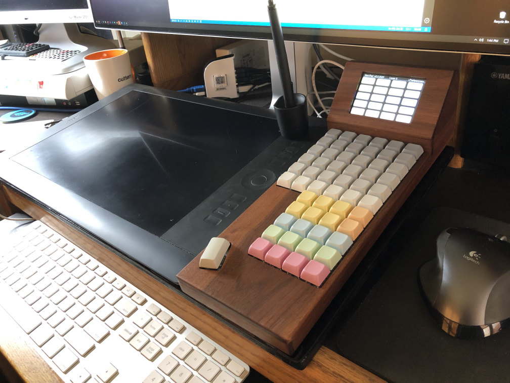
My workstation layout involved a chiclet-style wired mac keyboard (butterfly switches) on a Linux/Windows workstation with a large Wacom graphics table placed above it. I’m left-handed, so this leave me more space on the right side of the tablet near the mouse. I am then able to quickly move my hand between the mouse and keypad with minimal distance travelled.
My main requirements included:
- Vertical layout to allow placement between tablet and mouse.
- “Thumb Section” for a meta-key such as Control or Shift for a left-handed artist such as myself.
- “Primary Section” for the most often-used keys to avoid searching that would be accociated with a display or those keys’ functions.
- “Secondary Section” for less often used functions with buttons that would be labeled.
- All code self-contained within the system without drivers or external OS-specific applications. This would make it truly portable.
I considered adding several optical encoders with knobs for dial-type functions but decided that those might be better served with a separate box in the future.
The various parts of this project included…..
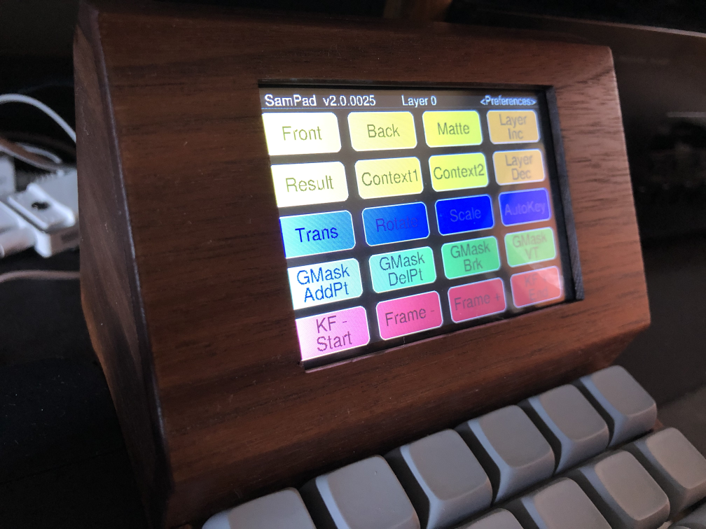
The Display:
I considered having a tiny OLED display for each button for best labeling of the keys. This allows the most flexibility in layers of keys and the ability to change everything purely by software. However, testing with the smallest OLED display I could find led to many issues, such as….
- .9 Inch OLEDs are expensive, and the circuit boards to which they are attaches add up to far too much space around them, limiting the closeness of the buttons. Most of they also use hard coded addresses, making it difficult or unwieldy to have dozens of them in a system without tying up many processor IO pins. They are also subject to burn-in relatively quickly. They do look nice, though.
- Multi-Row LCD character displays are also too large and don’t have high-enough resolution to display more than a few characters per key in my configuration.
- OLED Switches. I’ve tested several of these at trade shows. They are very tall, blocky, have a terrible feel for a keyboard and are VERY expensive—usually$30-$90 in bulk.
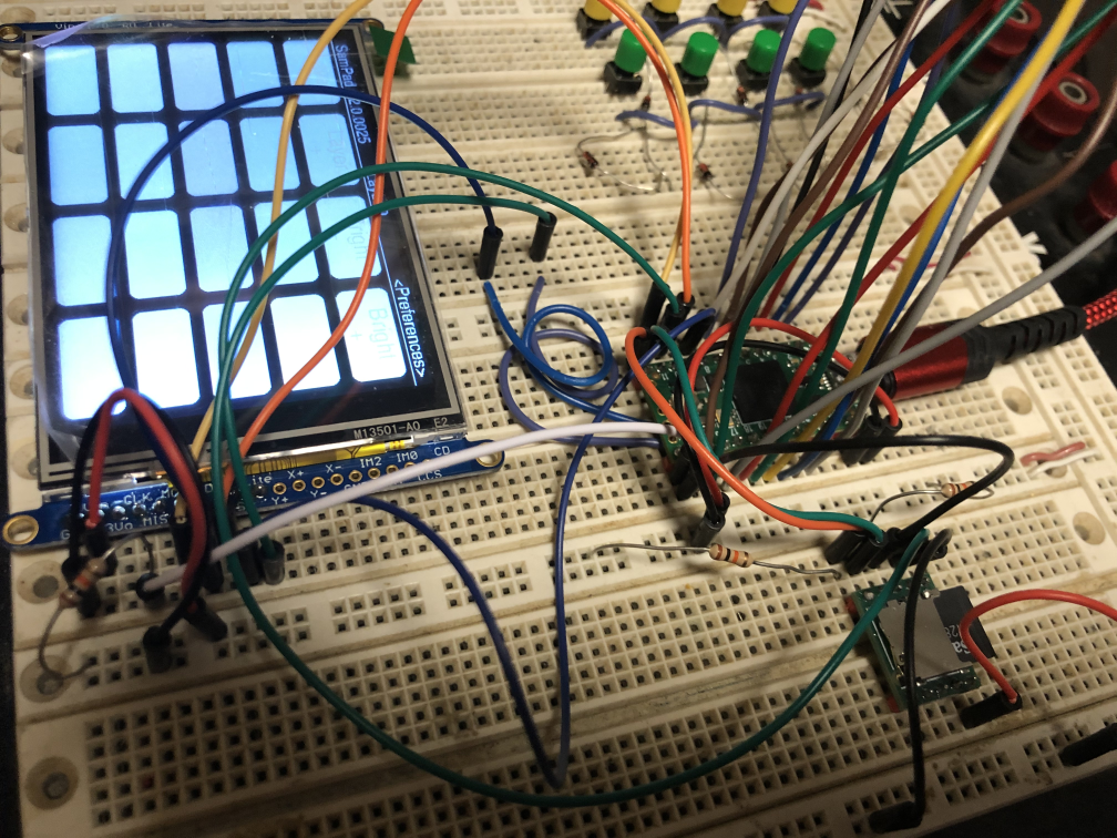
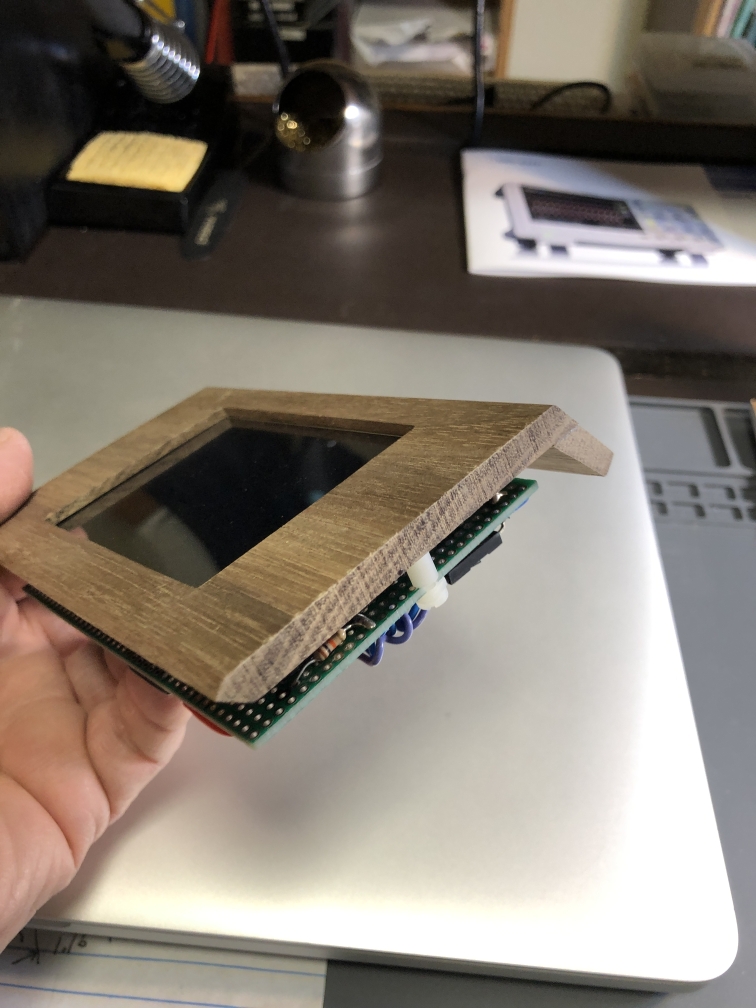
- TFT LCD Displays. These seemed like a good compromise. These is some wasted space around the borders for circuit boards, but could be obtained in 3-1/2” screen that had good resolution and color, SPI and I2C controllability and low cost at less than $I2C controllability and low cost at less than $40.
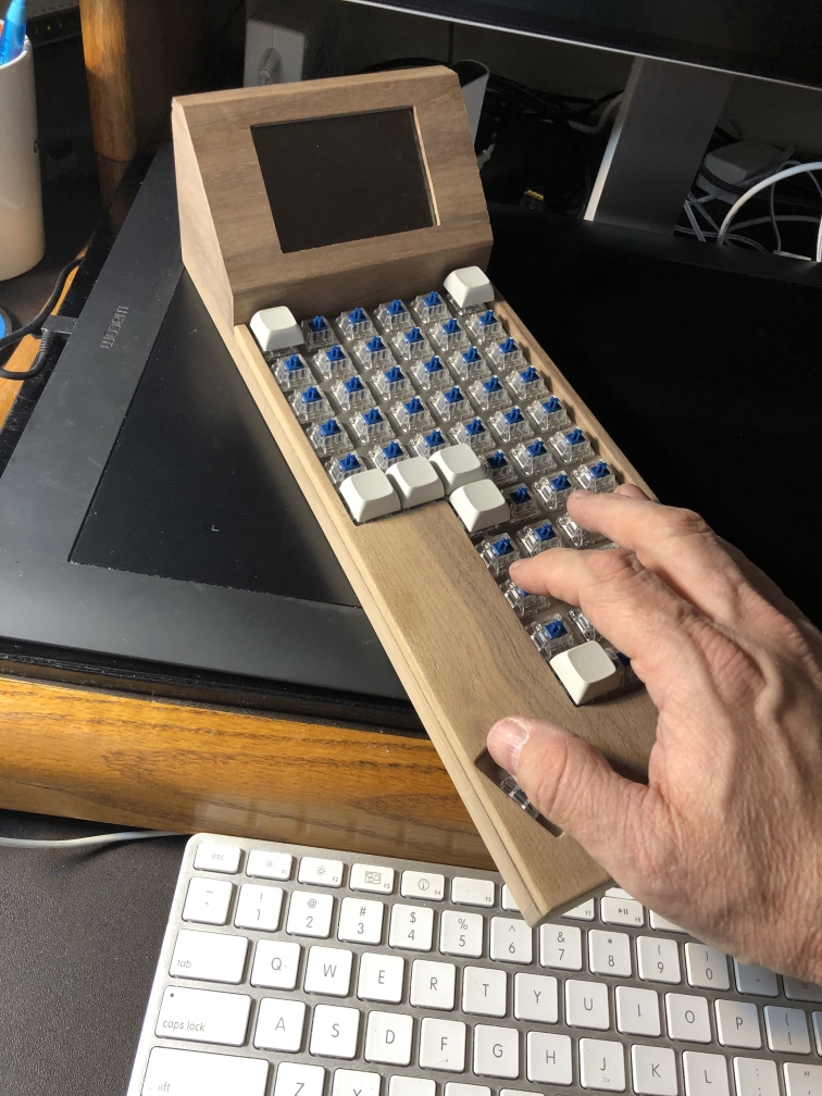
After trying each of these I settled on the TFT LCD. At the design distance of approximately 18-24” inches from my eyes, these are very legible. The Display helped dictate the overall layout of the Keypad.
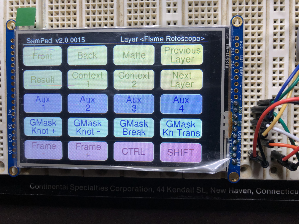
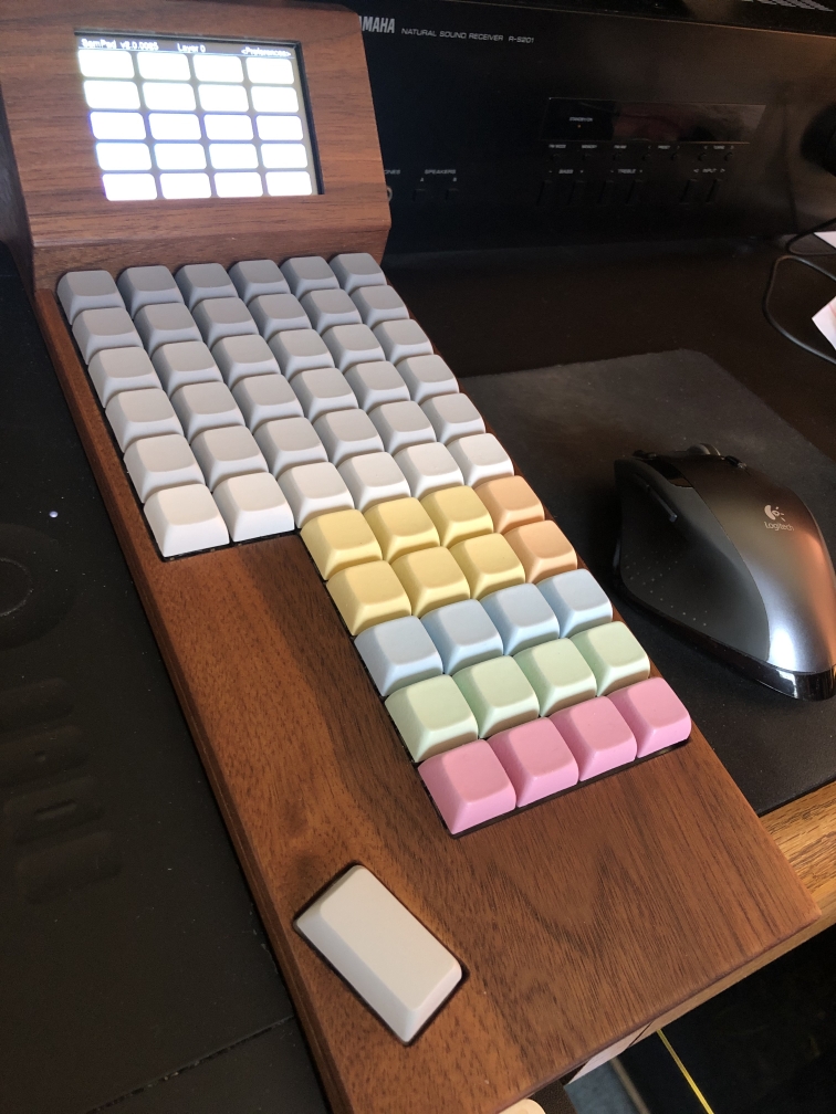
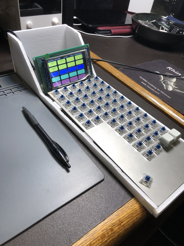
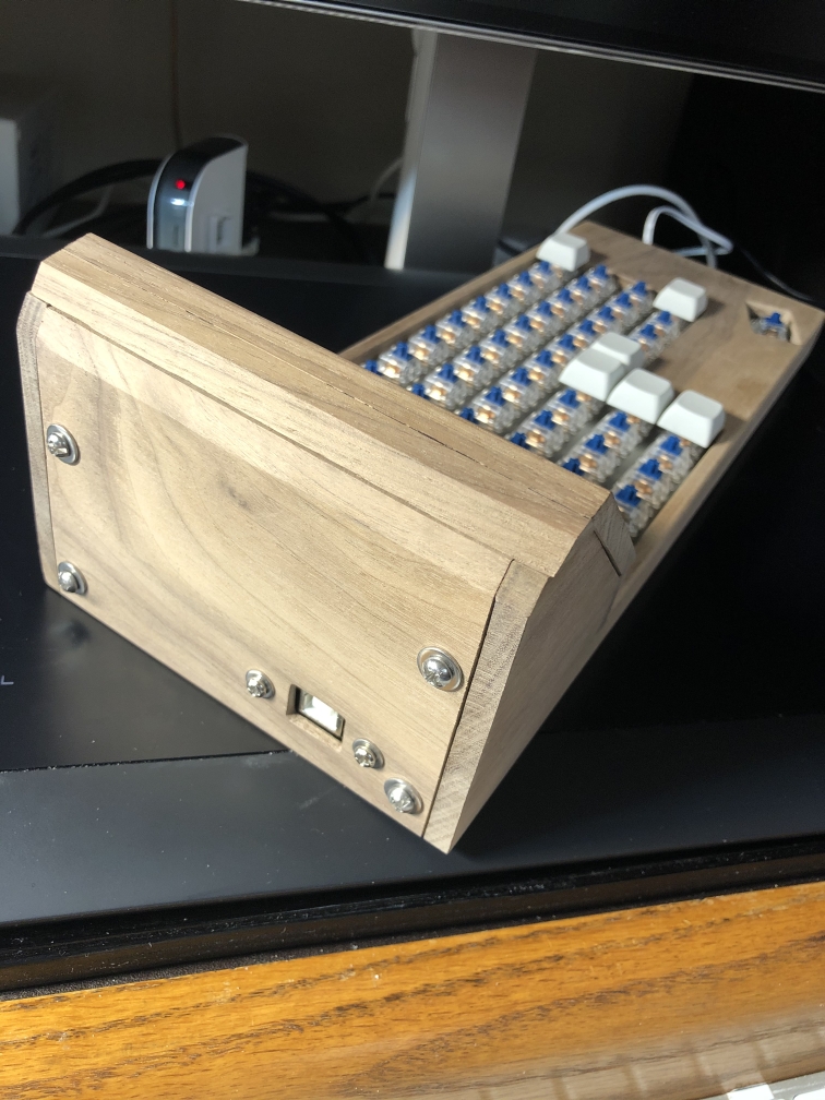
The Layout
- With an upright display and the information that would fit on it at a given time, I decided to make the keypad have three main ‘sections’. The top would be keys that could be labeled with more or less permanent functions. The middle section would be keys with no labels, but their function would be displayed on the LCD, allowing me to change their functions via ‘layers’ of macros. These would be color coded to the display. The bottom section would be a Thumb switch for meta-type functions such as shift or control.
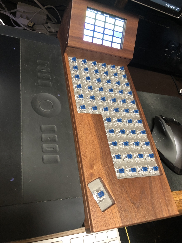
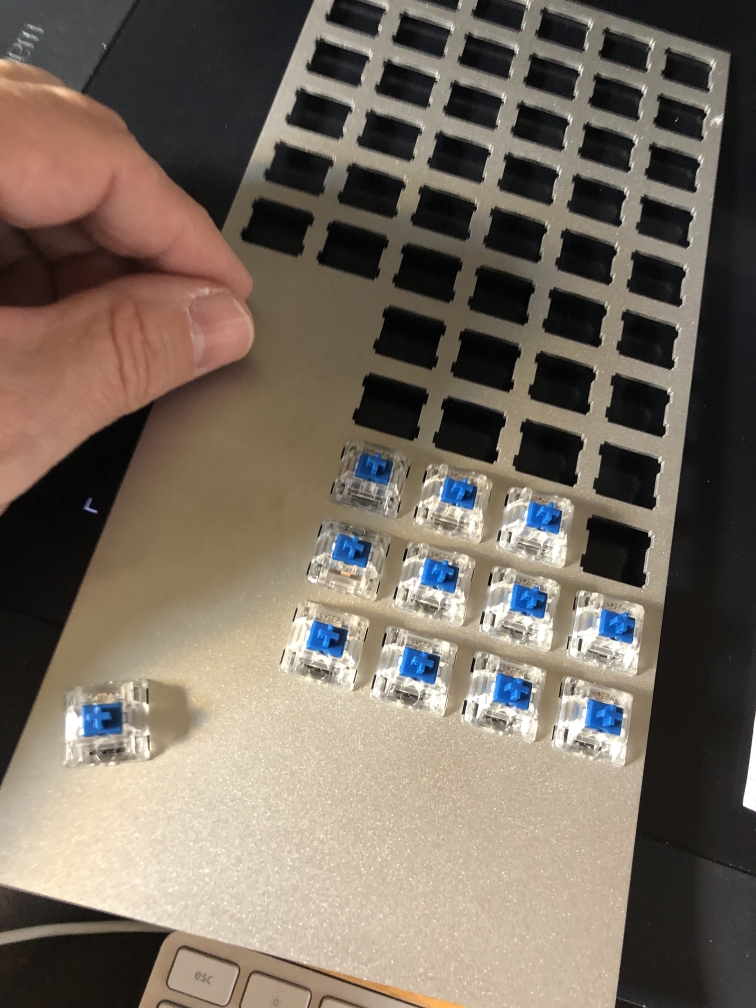
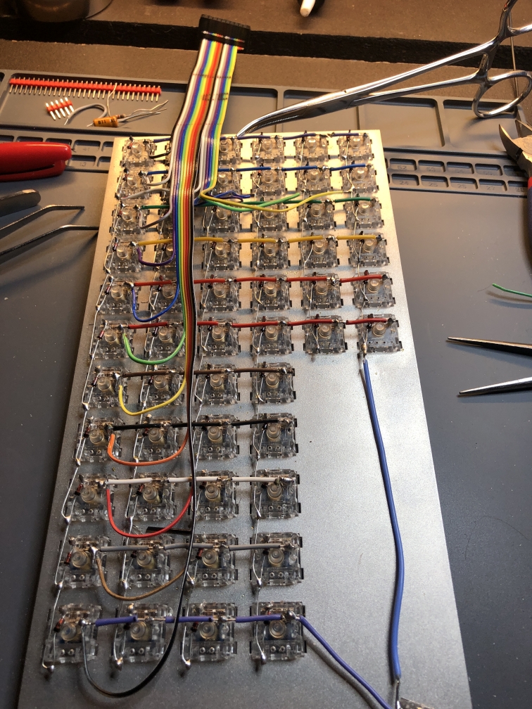
Switches & stainless steel mounting plate
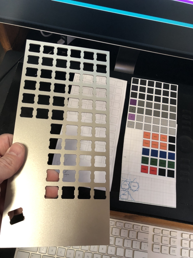
I elected to use a stainless steel keyboard plate to hold the switches for maximum stiffness. I drafted up a properly dimensioned CAD for the plate in Rhino-3D with all the proper spacing for switch holes and sent it to a company in Spain that laser-cuts 1.5mm stainless steel plates. All the wiring would be done by hand by me under the plate-mounted switches. This is a good compromise for a one-off project such as this. It would have been interesting to have a service created a circuit board created by me, but not worth the expense for a single device.
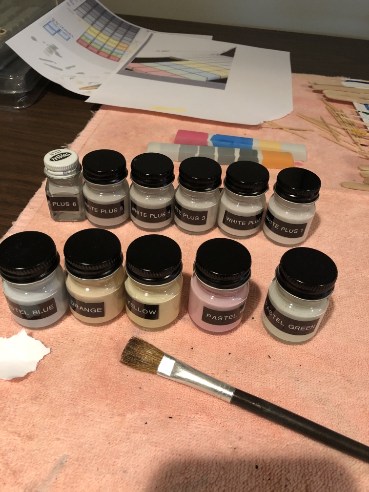
Keycaps
XDA keycaps give a bit more room for labeling and are a nice design. I considered molding my own lower profile keycaps from resin but it seemed unnecessary since I could not find lower throw switches that I liked. By avoiding “row-based” standard keycaps for keyboards I was able to avoid needing specific keys for specific rows which helps with my vertical layout. All keycaps are physically identical. XDA keycaps are very difficult to find in specific colors, and white individual keys were extremely tough to find. I tried dyeing the keycaps but settled on painting them with a thinned enamel to get the exact colors I wanted. I tested water-slide decals and vinyl labels for the permanent keycaps as well. My final paint tests led me to a mix of enamel paint to get my desired colors, and a clear coat of plasti-dip liquid rubber to protect the keys and give them a tacky feel.

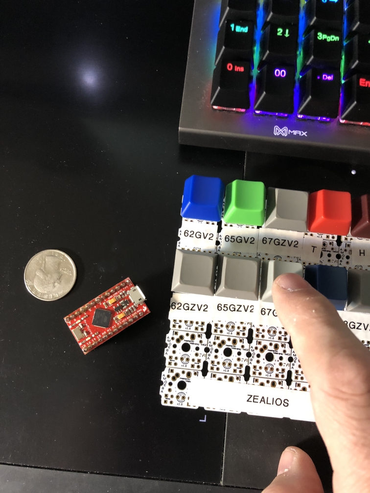
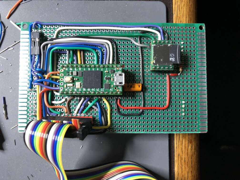
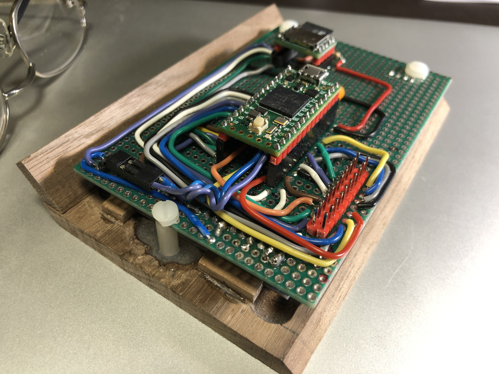
Processor
I prototyped with an Arduino Pro Micro but it didn’t have enough digital IO pins. I didn’t want to complicate things with io expander chips. I then ordered an Arduino Elite-C since it had more IO. This was a mistake. I could find no documentation for it and the companies distributing it had none and would share no additional info. I then locked into the Teensy 4 microcontroller. More or less compatible with the Arduino type controllers, it has much more IO, more memory, is far faster and an overall more versatile chip. As I frequented the Teensy online forums, I found the members (and designer of the Teensy) professional, extremely willing to help and overall had a wonderful experience learning the chip and its nuances. There are also several versions of the Teensy hardware available. I recommend it highly.
Programming Environment
As I approached the project I started using the Arduino Integrated Developer Environment for the first time. Ugh. What a horrible excuse for an IDE. I explored several others, both commercial and free. More Ugh. Some were barely supported, others were so complicated to set up that you needed to spend more time on that than developing. What I really wanted was a duplicate of the Microsoft Visual Studio.NET IDE. There were plugins for the VS IDE for Arduino but they were all pretty horrible. Then I stumbled onto PlatformIO, a plugins system for Visual Studio Code. VS Code is similar to VS.NET. It isn’t nearly as nice as VS.NET but it’s the closest I could get. VS Code suffers from what I think of as the need for developers to turn solid applications into Web-type apps, with links instead of buttons and more of an ‘online look and feel’. I setup PlatformIO with VS Code and it was the best choice I could get for C++ development on the Teensy. The C++ was overall fairly standard and the object oriented aspects of the Teensy/Arduino platform feel familiar if you’ve done C++ programming before. Once you’ve used Visual Studio.NET for as long as I have, anything else seems like going back to the stone age by comparison so it was well worth the investment in time for learning PlatformIO/VSCode.
Software
I wanted to avoid OS-specific compatibility problems and that meant not having to use OS-specific drivers. Therefore, all the software and key information would have to be kept within the embedded processor. There are several keyboard apps and libraries out there for Arduinos but my experience with open-source always has me “chasing” other people’s updates or sacrificing my features. I decided to write the entire embedded processor application/code myself. This costs me maximum work up-front but gives me the ultimate in flexibility in the long-term. I attempted using some of the Arduino keypad libraries but had to modify those libraries because of several limitations I found. Most of the time I found I benefited from investing the time in writing my own libraries whenever possible. There were also some bug in the open source Keypad.h libraries that had trouble with certain size matrices of switches, so I customized those a bit to match my layout.
Case
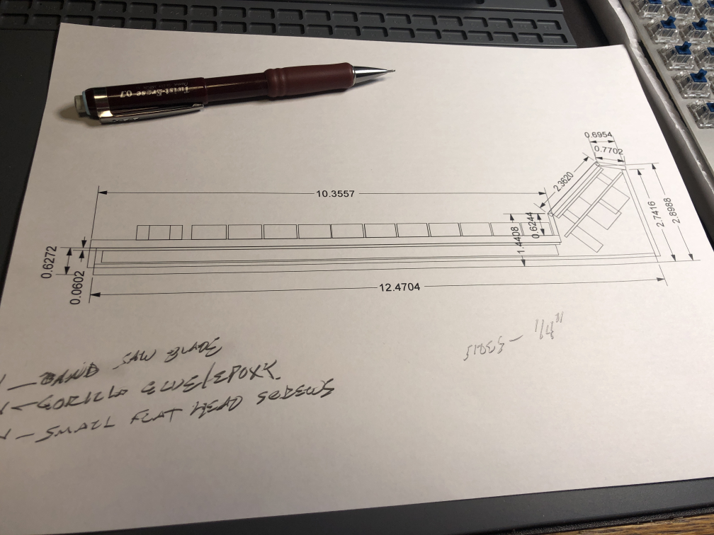
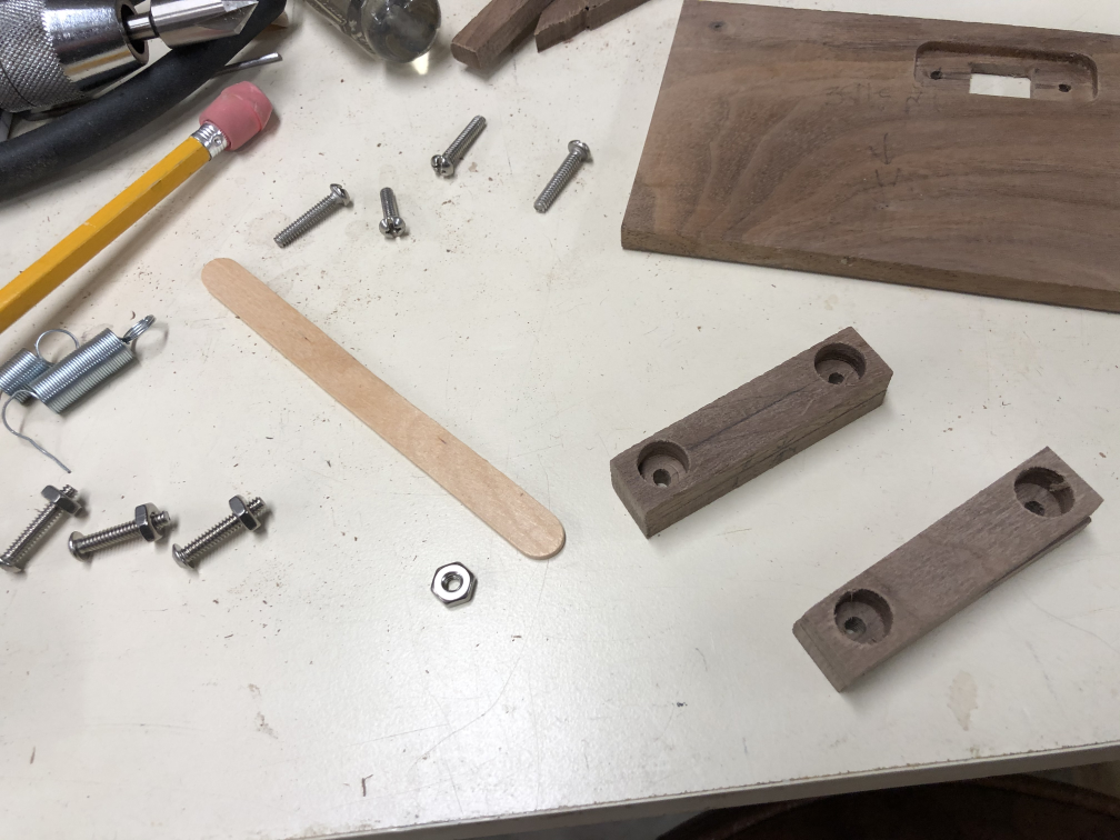
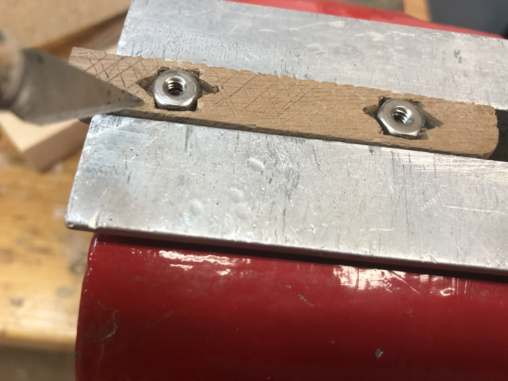
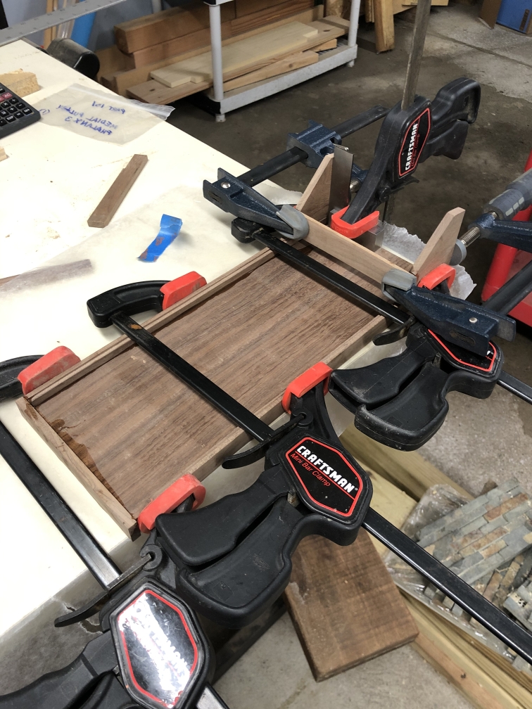
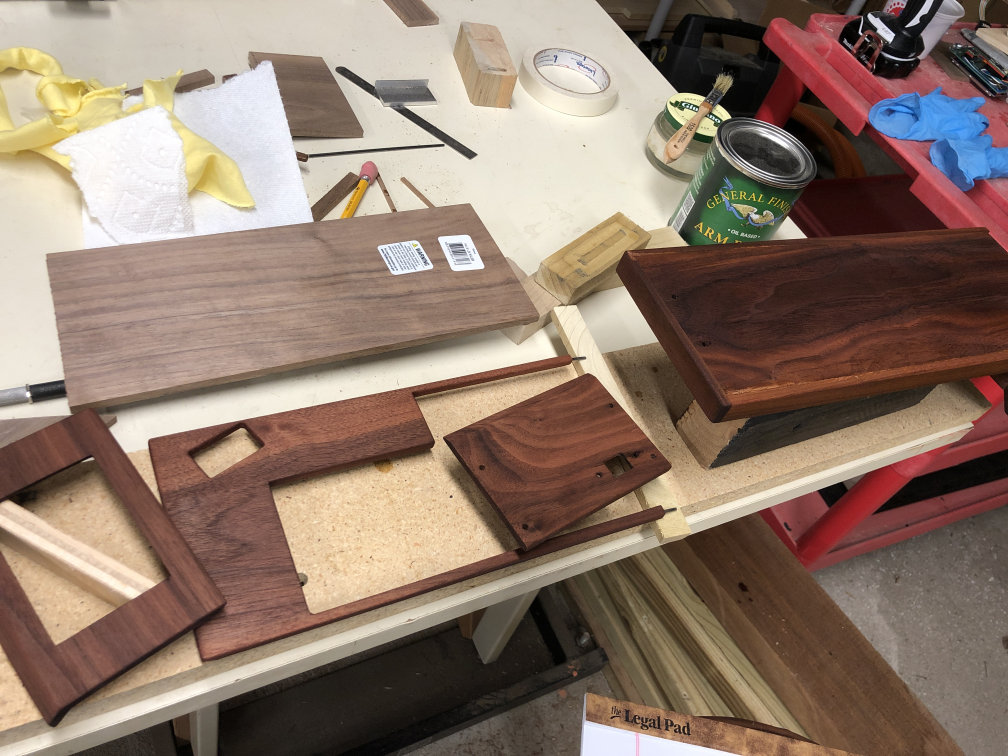
This became a bit of a project unto itself. I originally wanted to mill the entire case from a billet of aluminum 7075 and make some Titanium accents for the corners. However, my Sherline CNC Mill was a couple inches too small to work the metal, so I switched to Wood as the primary material. I’d never worked with Black Walnut before so that was a good place to start. A lot of woodworkers shy away from walnut that has sapwood in it, but I really liked the look of the lighter wapwood streaks through the darker heartwood. I wound a few pieces that had this nice contrasting streak through them for the top panel. Most of the case is 1/4″ and 1/8″ Black walnut. I started with a foam board mockup to nail down the sizes, then CAD refined it in Rhino 3D for measurements. Most of the cutting was done on my bandsaw and details were milled on my Sherline Mill or chiseled by hand. Attachements were made by using epoxy on captive stainless steel bolts and all other hardware was stainless steel.

Case Finish
The final finishing of the case was quite a process. Here is what was involved:
- Disassemble everything, being careful to label all hardware and pieces.
- Reassemble all the wood case (without the switches and computer hardware) for final sanding to avoid dust contamination of the switches and display.
- Medium sand all wood to 150 grit and round sharp edges.
- Wet all surfaces with distilled water to raise the grain, waiting 4 hours to dry.
- Another light sanding with 150 grit to smooth.
- Scrape all surfaces with hand scraper for clean, sharp cut wood fibers without plugging the grain as can be caused by sanding.
- I then dyed the walnut with a mix of 90% alcohol and a tiny amount or dark orange dye powder. This gave a hint of warm tone to the wood.
- Now a finish coat of General Finishes Arm-R-Seal satin oil topcoat. I brush this on thin, then wipe the excess off after 2 minutes of soaking in. Like most Oils, this adds a bit more yellow/warmth to the already dyed wood. 3-4 coats of the oil are applied like this, each brushed on and wiped off with 24 hours between each to dry completely. In addition, I wet sand between each coat with wet sandpaper and mineral spirits very lightly to remove any dust bumps. No sanding after the final coat of oil is needed.
- After the final coat, the case pieces are left to cure in a dry room for a minimum of 2 weeks. Oils take a long time to cure.
Final Assembly